Industrial CT • Computed Tomography • 3D Analysis

Industrial CT scanning: computed tomography and CT metrology systems.

Industrial CT systems and contract CT analysis to see inside a part without cutting it, from casting porosity to assemblies inspected as built and internal dimensions compared against CAD.

Quote within 24 hours · CT system or contract service · Trial scan can be arranged

Quick answer

What is industrial computed tomography (CT)?

Industrial computed tomography (CT) is an X-ray non-destructive test: the part rotates in the beam and the projections collected are reconstructed into a 3D volume. It is the method of choice when you need the position and volume of internal flaws, or dimensions no touch probe can reach, on castings, additive manufacturing parts, plastics and assembled units.

We help you choose the right CT system or service: quote within 24 hours

How much does industrial CT cost?

It depends on whether you need a CT system in your plant or a scan through the contract service. For a system, source energy, resolution, part size and software drive the price; for the service, the number of parts and the analyses required. Tell us what you need to inspect and we’ll prepare a quote within 24 hours, for the system or the service.

  • Quote within 24 hours
  • Priced per system or per scan
  • Custom systems for your application
  • Porosity, metrology and assemblies
Computed Tomography

From the part to inspect to the right system.

We start from the component and what you need to see or measure, then point you to the right family of CT systems or to the contract analysis service. When a standard system is not enough, we design a custom CT system with the manufacturers around your application.

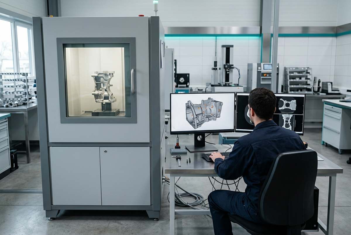
industrial CT system for 3D component inspection
Computed Tomography

Industrial CT systems for non-destructive inspection

CT reconstructs the full volume of the component, and the same 3D data set yields porosity and internal defects, measurements against CAD, assembly checks and geometry for reverse engineering.

  • Castings, plastic moldings, composites and complex components.
  • Internal inspection without cutting the part.
  • Support in choosing between a cabinet system, a microfocus source and analysis software.
Our products

CT systems and CT scanning service

A system of your own, configured around the parts you inspect, or contract CT analysis when you only have a few parts.

Applications

Where industrial CT is used.

AerospaceAutomotiveFoundriesAdditive manufacturingPlastic componentsAssembliesR&DQuality control
CT inspection

What industrial CT scanning can measure.

The part rotates in front of the X-ray beam and the projections are reconstructed into a volume of voxels, the small cubes that play the role of pixels in 3D. The volume yields internal defects, with their position and size, and measurements, including surfaces no probe can reach.

Porosity and voids

For every pore CT gives volume, shape, position and distance from surfaces still to be machined, which for a sealing face matters more than the overall percentage. To see why two reports can disagree, read the case of two labs measuring different porosity on the same casting.

Inclusions and foreign bodies

An oxide or core fragment in a casting, a metal particle in a polymer: anything denser than the matrix shows up brighter, the rest darker. Between materials of similar density the contrast drops and detectability has to be proven on a sample.

Assemblies

Springs, seals, clearances and presence of components are checked with the assembly as built, in the condition it works in. Metal inside a plastic housing leaves streak artifacts that software reduces without removing them.

Dimensional metrology and CAD comparison

The surface extracted from the volume is compared with CAD in a color map, and dimensions can be measured on internal channels and cavities too. Accuracy has to be proven with acceptance tests and an uncertainty stated feature by feature, as the article on CT metrology of internal geometries explains.

Plastics and composites

Polymers attenuate X-rays weakly, so low tube voltages are enough to show voids, weld lines and molding distortion. In composites, fiber orientation and delamination show up as well.

Additive manufacturing

In printed metal parts CT finds gas porosity and lack-of-fusion porosity, powder trapped in channels and deviations from CAD. On lattices and conformal channels it is often the only non-destructive check that can reach them.

For castings there is the article on porosity in castings and die castings with CT, while the technical guide to industrial CT scanning covers scan parameters and artifacts. For parts without a drawing there is CT reverse engineering, from STL mesh to CAD, and for moldings, polymers and laminates the article on CT scanning of plastic and composite parts.

System selection

Which CT system for which part.

In CT it is the part that sets the resolution. When it fills the detector, the voxel is roughly the imaged diameter divided by the number of pixels, so a part twice as wide has a voxel twice as large. The smallest detail you need to see tells you which of the four families you fall into.

Comparison of industrial CT systems: micro-CT and nano-focus, standard cabinet CT, high-energy CT for large parts, inline CT
SystemPart size and materialTypical resolutionApplicationsWhen to choose it
Micro-CT and nano-focusSmall parts or samples: plastics, light alloys, electronics, compositesThe finest, over a small field of viewMicro-porosity, fibers, solder joints in electronics, small 3D-printed partsVery small defects on small parts or samples
Standard cabinet CT (microfocus)Benchtop parts: light-alloy castings, plastics, assemblies, additive partsHigh on mid-size parts, dropping as size growsPorosity, assemblies, CAD comparison, wall thicknessQuality lab with varied parts: the most versatile
High-energy CT for large partsSteel and cast-iron castings, housings, energy and aerospace componentsCoarser: macroscopic defects, shrinkage, wall thicknessCavities and shrinkage in large castings, assemblies that cannot be taken apartWhen a cabinet cannot penetrate the part; needs a shielded bunker and radiation protection
Inline CTSeries parts with constant geometry: die castings, plastics, battery cells and modulesLimited, traded off against cycle time100% inspection or extended sampling with automatic evaluationWith high volumes, a validated reject criterion and a need for 3D data that radioscopy cannot provide
Standards and guidelines for industrial CT

Non-destructive testing standards govern the examination, coordinate metrology standards govern the measurement, and a good specification keeps them apart.

  • ASTM E1441-19(2026), guide to computed tomography with principles and performance parameters, but no acceptance criteria.
  • ASTM E1570-19(2026), fan-beam CT examination and minimum requirements for placing a system into service.
  • ISO 15708-1:2024, the computed tomography vocabulary.
  • ISO 15708-2:2025, on principles, equipment and samples.
  • ISO 15708-3:2025, on how the examination is run and how results are interpreted.
  • ISO 15708-4:2025, dedicated to qualification.
  • VDI/VDE 2630 Part 1.3 (December 2011), which applies ISO 10360 to coordinate measuring machines with CT sensors.
  • VDI/VDE 2630 Part 2.1 (June 2015, corrigendum 2023), on measurement uncertainty and measuring process suitability.

None of them sets how much porosity is acceptable, because that limit is agreed on the drawing or in the specification.

If you have one or a few parts to investigate, the contract CT scanning service is the sensible route, while routine scanning makes an in-house scanner worth considering. The cost comparison is in the article industrial CT, buying a system or using a service. For inline inspection there is the article on when industrial radioscopy pays off, and for welds and field work the page on industrial radiography with X-ray, CR and DR systems.

CT system or outside service, assessed on your part

Send us a drawing or photo, the material and what you need to see or measure. We will tell you whether a CT system or the contract service makes more sense, with a quote within 24 hours.

  • CT systems and contract service
  • Micro-CT, cabinet, high-energy and inline
  • Trial scan can be arranged
DIPITECH approach

Application first, technology second.

We look at the part, the material, the resolution you need and where the inspection will sit in your quality process, and only then talk about machines.

What to send us for an evaluation

  • Material, size and weight of the part.
  • The smallest detail to see or the dimension to measure, with its tolerance.
  • Analyses required: porosity, metrology, assembly, reverse engineering.
  • How many parts and how often.
  • A drawing or CAD file, if available.
  • Whether you need an in-house system or the contract service.
Technical criteria

How to choose an industrial computed tomography system.

A CT system is sized around the part, the material and the goal of the inspection, which may be finding defects, measuring or both. These are the parameters we assess with you before proposing a system.

Part size and measurement volume

Size and weight of the component decide the manipulator and the achievable magnification, and therefore the voxel size. A small part moves closer to the source and gains resolution, a large one needs other energies and other scan geometries.

Energy and penetration

The material and the thickness to penetrate set the source energy, expressed in kV or MeV. Thick steel and cast iron need far higher energies than plastics and composites.

Resolution and voxel size

Which pores, inclusions or cracks you can see, and how precisely you can measure, depends on voxel size, focal spot and detector.

Defect analysis vs metrology

Finding defects and measuring dimensions are two different jobs. Defect analysis depends on contrast and detectability, metrology on a verified system and a known uncertainty, and software and configuration follow from that.

Software and reporting

Porosity analysis, wall thickness maps, nominal/actual comparison and reports are all done in software, which matters as much to the result as the source and the detector.

Throughput and integration

Scan time, automatic loading and the link to the quality system decide how many parts are actually inspected per shift. A lab, a quality department and a production line lead to different choices.

Related technologies include industrial radiography (X-ray/CR/DR) and XRF/PMI material analysis. More articles are in the NDT technical resources.

To see when CT is the right choice compared with other methods, read the page on non-destructive testing methods and how to choose them.

FAQ

Frequently asked questions on industrial computed tomography

What is industrial CT used for?

It shows the inside of a component without destroying it, to find porosity, inclusions and cracks, check fully assembled units and measure the part in 3D against CAD.

What resolution can I achieve?

It depends first on the size of the part, because a small component can be magnified more and gives finer voxels. Focal spot, energy and detector set the rest. Tell us the smallest defect you need to see and we will tell you which family of systems can reach it.

Is CT used for castings and additive manufacturing?

Yes, these are among its most common uses. In castings it looks for porosity, and in additive manufacturing it qualifies internal channels and lattices, where defects cannot be seen with other methods.

CT for defects only, or also for measurement?

Both, including internal dimensions a probe cannot reach. If measurement is the goal, you need a verified system and metrology software, so say so before choosing a system.

CT or industrial radiography: which one do I need?

It depends on what you need to know. Radiography gives a 2D projection quickly and is the standard for welds, field inspection and, as radioscopy, for series parts at 100%. CT reconstructs the volume, with depth and 3D size of the defect and the dimensions of the part, but a scan takes from minutes to hours. That is why they often work together, radiography for screening and CT on doubtful parts.

Can CT measure porosity as a percentage?

Yes, the software separates pores from material and relates their volume to the analyzed region. The figure only means something together with its measurement conditions: voxel size, segmentation method and threshold, region of interest. Pores below a few voxels are missed, and two voxel sizes give two different percentages on the same casting, so fix these conditions in the specification. The topic is developed in the article on measuring porosity with CT.

Does industrial CT work on plastics and composites?

Yes, and it is where CT reaches its finest detail. There are two limits. Metal inserts leave streak artifacts, and between materials of similar density, such as carbon fiber and resin, contrast drops. Glass fibers, being denser, separate from the resin better than carbon fibers.

Should we buy a CT scanner or use a CT scanning service?

The choice depends mostly on volumes. With a few parts a year or a one-off problem a service is usually the better choice, while with routine scans, critical turnaround or confidential parts an in-house system starts to pay for itself. DIPITECH offers both CT systems and a contract CT scanning service, and can arrange a trial scan on your part before you decide. The numbers, item by item, are in the article on when buying a CT system pays off.

How do I request an evaluation?

Send us the material, the part size, the defects or dimensions to check and how many parts you inspect. We will point you to the right CT configuration, or to the contract service, with a quote within 24 hours. You can use the form below or WhatsApp.
Application support

Technical support, installation and training.

Once the system is chosen, we help you define the project and follow you through the next steps.

Solution configuration

Technical requirements, accessories, analysis software and documentation defined around the application.

Start-up and installation

Installation, commissioning and first trials on your parts, coordinated with the manufacturer.

Operator training

Initial training, support during first use and connection with the manufacturer for service and spare parts.

Contact

Let’s find the right CT solution for your parts.

If you need to choose between a CT system and a contract service, or find out whether CT can see the defect you care about, DIPITECH Industrial Solution helps you clarify the requirement, compare the options and arrive at a concrete proposal.

Application request

Tell us about the part to inspect.

Include material, size, what you need to find or measure and your yearly volumes.

WhatsApp