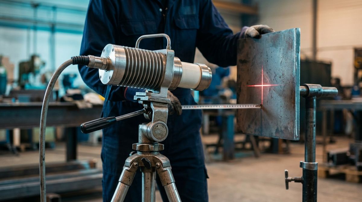
What an X-ray tube is. It is the component that produces X-rays. Inside a vacuum envelope the cathode emits electrons, the high voltage accelerates them toward the anode, and on impact a small part of their energy becomes X-radiation while the rest turns into heat. kV sets the maximum photon energy, mA the photon output, and the focal spot, together with the distances, the sharpness of the image.
Two radiographic systems with the same maximum voltage can produce images of very different quality. The number on the nameplate matters less than quantities catalogs rarely advertise: focal spot, exposure geometry, high-voltage waveform, filtration, anode heat capacity. Those are what decide what the image will show. If you are choosing a tube, the commercial criteria are in our guide on how to choose an X-ray tube and generator. This article covers the physics behind each parameter, with the arithmetic worked out. The industry's reference vocabulary is ISO 5576:1997.
Focal spot and geometric unsharpness: where everything starts
The beam comes from an area of the anode, the focal spot, whose projection in the beam direction is the effective focal spot. The anode angle makes it smaller than the area actually struck by electrons. Because the source has a finite size, every edge of the part casts a blurred transition zone on the image, geometric unsharpness Ug, given by a simple formula.
Ug = f · b / a, where f is the focal spot size, a the source-to-object distance (SOD) and b the object-to-detector distance (SDD − SOD). Equivalently, Ug = f · (SDD − SOD) / SOD.
An example with round numbers. With a 2.0 mm focal spot, the part 600 mm from the source and the detector at 660 mm, so b = 60 mm, unsharpness is 2.0 × 60 / 600 = 0.2 mm. If the same part is radiographed 300 mm from the source, with the detector still 60 mm from the part, unsharpness doubles to 0.4 mm. Fine detail, such as small pores and thin IQI wires, then starts to blur. That is why ISO 17636-1 and ISO 17636-2 impose minimum source-to-object distances, based on focal spot, thickness and technique class, with class B stricter than class A. In radiography, geometry is a requirement of the standard before it is a matter of convenience.
Read the nameplate value with care, because the nominal focus and the measured spot may not match. For industrial systems the measurement was long governed by the EN 12543 series, withdrawn in Europe between 2025 and 2026: parts 2, 4 and 5 were replaced by EN ISO 32543-1, -2 and -3, while parts 1 and 3 were withdrawn without a direct successor. Part 1, from 2024 and adopted as EN ISO 32543-1:2025, uses a pinhole camera for spots above 0.1 mm; Part 3, from 2026, covers mini and microfocus tubes from 5 to 300 µm up to 225 kV. On the ASTM side the counterparts are E1165-20, for spots from 100 µm to several millimeters, and E2903-18(2024), which states it is based on EN 12543-5. Two "1 mm" tubes measured by different methods can behave differently, and the first question for the supplier is about the method.
Minifocus and microfocus: when magnification works for you
A smaller focal spot also lets you exploit projective geometric magnification. Moving the part closer to the source enlarges the image by a factor M = SDD / SOD, and at the detector plane unsharpness becomes Ug = f · (M − 1).
With a 5 µm microfocus tube, the part 30 mm from the source and the detector at 300 mm, magnification is M = 10 and unsharpness at the detector is 5 × 9 = 45 µm. With a 100 µm pixel panel, the pixel referred to the part drops to 10 µm. That is enough to resolve voids in ball-grid solder joints, bonding wires or internal channels in a 3D-printed part. The same magnification with a conventional 1 mm tube would give 9 mm of unsharpness, an unusable image. It is the focal spot and magnification pair that sets the real resolution of the system, more than the detector alone. The price is paid in flux, because microfocus tube power is measured in watts rather than kilowatts and exposure times grow.
There is no single number carved into a standard between the categories. The ISO 32543-4 and 32543-5 drafts in preparation treat spots below 100 µm as microfocus, and ASTM E1165-20 starts its standard and mini spots at exactly 100 µm. The 50 µm threshold found in some texts has no support in these documents. When a supplier says "microfocus", ask for the measured size, the method and the voltage it applies to. For the panel to pair with it, see how to choose a DR detector, and for high-resolution volumetric imaging the industrial CT scanning guide.
kV: energy, contrast and thickness
Tube voltage sets the maximum photon energy, and with it penetration and contrast. At lower energies photoelectric absorption dominates, strongly dependent on thickness and atomic number, so thickness differences turn into large signal differences. As energy rises Compton scattering takes over and the image flattens. Hence the practical rule of the lowest kV compatible with the penetrated thickness and reasonable exposure times. ISO 17636-1 publishes curves of maximum permissible voltage by thickness and material, to be read as a ceiling, well away from the working value.
NIST attenuation coefficients show the size of the effect. In a narrow beam, at 100 keV one centimeter of iron attenuates as much as about 6.4 centimeters of aluminum. At 200 keV the ratio drops to about 3.5, because the photoelectric effect, sensitive to atomic number, gives ground to scattering. A 40 mm aluminum casting, although thicker than a 20 mm steel weld, is therefore radiographed at much lower voltages. Running aluminum at the tube's maximum "because it's there" produces a flat image in which fine shrinkage porosity disappears. The everyday tool remains the system's exposure charts, kV, thickness and mA·min diagrams built for your own tube, distance and detector, to be redone whenever one of the three changes.
Do you need to size tube and geometry for your application?
Send us materials, thicknesses, part sizes and volumes: we will recommend voltage, focal spot and detector, with a tailored quote within 24 hours and a test on your own material.
Email us Message us on WhatsAppmA·s, reciprocity and filtration
At equal kV, the amount of radiation is proportional to current multiplied by time, in mA·s or mA·min. Within wide limits 5 mA for 2 minutes equals 10 mA for 1 minute, and the choice depends on the tube's heat capacity and site constraints. Added filtration, thin copper or aluminum sheets at the window, removes the low-energy tail of the spectrum, photons that would not get through the part anyway but generate scatter and fog. The hardened beam improves the contrast-to-fog ratio on medium and heavy sections and is often required by procedures, at the cost of slightly longer exposures. On the detector side the counterparts are lead screens, with film, and backscatter control.
| Parameter | Main effect | Practical rule |
|---|---|---|
| Focal spot (f) | Sharpness: unsharpness Ug = f·b/a | Small for detail; large for power and short exposures |
| SOD / SDD | Unsharpness and magnification M = SDD/SOD | Respect ISO 17636 minimum distances; magnify only with small spots |
| Voltage (kV) | Penetration and contrast, which move in opposite directions | Lowest practicable kV; maximum-voltage curves as a ceiling |
| Current × time (mA·s) | Amount of radiation, density or SNR | From exposure charts; reciprocity within thermal limits |
| Filtration (Cu/Al) | Beam hardening, less scatter fog | On medium and heavy sections and where the procedure requires it |
| Waveform (constant potential or unipolar) | Effective flux and spectral stability | Constant potential for throughput and repeatability; unipolar where weight and cost matter |
On site: a portable tube on a pipeline
The toughest case is radiography of girth welds on site, with dozens of welds a day, power from a generator set and wide temperature swings. Here the less glamorous nameplate figures matter. Beam energy is a small fraction of electrical power, and almost all the rest becomes heat in the anode. Gas-cooled or forced-air portable tubes therefore declare a duty cycle: some run continuously at reduced current, others need pauses comparable to exposure times when running at full output. On our own assumptions, 40 exposures a day of 2 minutes each, a tube that needs a pause equal to the exposure adds 80 minutes of waiting per shift compared with one that runs continuously. It's a calculation to make up front, when you organize weld radiography for a pipeline or a site.
Waveform matters just as much. Constant-potential generators keep the high voltage stable, so the whole exposure runs at full energy, with a repeatable spectrum and shorter times at equal nominal kV. Unipolar or pulsed circuits are simpler and lighter, but for part of the cycle they produce lower-energy photons, giving longer and less repeatable exposures. On site the choice is a trade-off between throughput and the weight someone has to carry.
Then there is the panoramic tube, which emits through 360 degrees perpendicular to its axis and, placed at the center of the pipe, exposes the whole joint in one single-wall exposure. It needs access to the center of the pipe, usually with a crawler in pipelines; exposure geometries and typical joint defects are covered in the typical cases of weld radiography. In Italy, using X-ray generators is also a practice regulated by Legislative Decree 101/2020, with a radiation protection expert, classified areas and training. The steps to plan before buying are collected in our guide to the cost and purchase of an X-ray system. On site, collimation and beam direction serve radiation protection as well as image quality.
Image quality is decided before you press the button
Focal spot and distances set the achievable sharpness, kV the contrast, mA·s the noise, filtration the fog. No post-processing software recovers unsharpness born of the wrong geometry, which is why tube parameters should be chosen starting from the part to be radiographed. Turning them into a concrete configuration, with maximum voltage, one or two focal spots, waveform, cooling, directional or panoramic design and the detector to pair, depends on your materials, thicknesses and volumes.
What to send us for an assessment
To propose the right tube, generator and detector we need these facts:
- materials and minimum and maximum thicknesses to penetrate;
- part size and weight, and the smallest detail to detect;
- working environment: bunker, cabinet or site, with available power;
- geometry: internal access to pipes, possible source-to-part distances;
- standard and technique class required (A or B under ISO 17636);
- volumes: exposures per day or per shift;
- tube and detector currently in use, if any.
You can send them by email to info@dipitech.com or on WhatsApp, with drawings or photos of the parts.
With these, we put together an industrial radiography configuration built around your parts, from generator to detector, with a tailored quote within 24 hours and the option to test the exposure on your own samples.
Request a quote
Leave your name, email, and a few lines about your application, with no obligation. We reply within 24 hours with initial technical guidance and a quote.
Frequently asked questions about the X-ray tube: how it works, focal spot and parameters
How does an X-ray tube work?
The cathode, a heated filament, emits electrons. The high voltage between cathode and anode accelerates them, and each one reaches the target with an energy that, in keV, equals the kV setting. As they slow down in the target, usually tungsten, the electrons produce a continuous X-ray spectrum, plus the characteristic lines of the anode material. Only about 1% of the energy becomes radiation. The rest is heat, removed by oil or water or, in portable units, by gas and forced air, and that heat is what sets the tube's duty cycle.
What is the focal spot of an X-ray tube?
It is the area of the anode the beam comes from, seen from the exit direction. Many industrial tubes offer two, a small one for detail and a large one for power, and switching from the first to the second to shorten exposures changes unsharpness as much as changing the tube. Declared values are comparable only when measured with the same method, today the ISO 32543 series for industrial systems.
How do you reduce geometric unsharpness without changing the tube?
By moving the source away from the part or bringing the detector closer, because unsharpness grows with the ratio between object-to-detector and source-to-object distance. Moving the source away has a cost: intensity falls with the square of distance, and doubling it means four times the mA·s for the same image. ISO 17636 sets a minimum source-to-object distance in any case, stricter in class B.
Why does raising kV to shorten exposure degrade the image?
Because at higher energies the photoelectric effect weighs less and Compton scattering grows: thickness differences produce less signal difference and scattered radiation adds fog. The effect is stronger on light materials; according to NIST coefficients, between 100 and 200 keV the attenuation ratio between iron and aluminum drops from about 6.4 to 3.5.
What is the difference between minifocus and microfocus tubes?
It comes down to focal spot size. In the most recent ISO documents microfocus means below 100 µm, while minifocus sits above that threshold, among the spots ISO 32543-1:2024 measures with a pinhole camera. Microfocus allows strong geometric magnification without losing sharpness, useful for electronics, micro-welds and additive parts, but it works at a few watts and with longer exposures.
When does a panoramic X-ray tube make sense?
When there are many girth welds and the center of the pipe can be reached, for example with a crawler in pipelines: one single-wall exposure covers the whole joint, instead of three or more double-wall exposures. If internal access is missing, or there are few joints, a directional tube remains the more flexible choice.