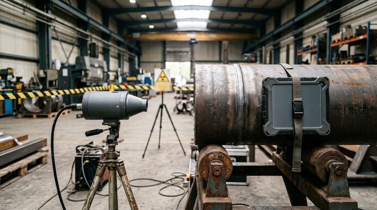
A short note shows up on the drawing, "RT 10%" or "100% radiography of butt welds", and from that moment someone in the shop has to turn it into actual work. You need a source suited to the thicknesses, a detector, a place to expose without putting anyone at risk, certified operators and a procedure that holds up when the customer or the notified body checks it. Weld radiography is among the most frequently specified non-destructive tests in structural steel, boiler and pressure vessel fabrication and plant construction, and it is also the one that takes the most organizing before the first exposure.
The starting point here is the work of whoever has to set up radiographic testing of welds and decide whether to keep it in-house or hand it to an NDT service company. Reading the defects has its own in-depth piece in the typical cases of weld and casting radiography, and rejection criteria are covered in the article on who decides the acceptance levels. The overall picture of the methods is on the non-destructive testing page.
Who requires radiography, and on how many joints
The obligation rarely comes from the radiography standard itself. It comes from the product code, the execution standard or the contract, and each of these documents sets in its own way how many joints to test and how to pick them. So the first useful question, even before talking about equipment, is which document governs the job.
For pressure equipment, the Pressure Equipment Directive 2014/68/EU requires in Annex I, section 3.1.3, that non-destructive tests of permanent joints be carried out by suitably qualified personnel. For categories III and IV that personnel must be approved by a third-party organization recognized by a Member State. In section 7.2 the directive then ties the joint coefficient to the extent of testing, with a value of 1 when tests confirm that all joints show no significant defects, 0.85 with random testing and 0.7 with visual inspection only. The radiography percentage thus becomes a design decision, because a lower coefficient is paid for with thicker walls. Harmonized construction standards, such as EN 13445 for unfired pressure vessels, translate these principles into detailed testing requirements.
For process piping designed to ASME B31.3, normal fluid service requires full examination of at least 5% of circumferential butt welds, by random radiography or random ultrasonic testing. The welds in the sample have to be selected so that each welder's work is included, and a rejected weld triggers additional examinations on that same welder's production. Whoever organizes the testing therefore needs to know who welded what, and traceability between joint number, welder and image becomes part of the inspection. In structural steelwork the percentage follows instead from the execution class of EN 1090-2, a path traced in the article on acceptance levels.
From specification to exposure: procedure, technique and IQI
Once it is clear how many joints to test, you need a written procedure that says how. The reference is ISO 17636-1 for film and ISO 17636-2 for digital detectors, both in their 2022 editions, with two technique classes. Class A is the basic technique and class B the improved one, more demanding on distances, sensitivity and number of exposures. Which of the two applies is set by the quality level required for the joint, while method selection and general rules are found in ISO 17635:2025.
The general procedure on its own covers little of the real work. Guidance from the UK Health and Safety Executive on procuring and conducting industrial radiography recommends supplementing it with technique sheets for each component, because different components call for different parameters. The sheet records exposure geometry, source with voltage or radionuclide, source-to-detector distance, detector type, number of exposures to cover the circumference, and the type and position of the image quality indicator. Single-wall and double-wall geometries, with the criteria for choosing between them, are described in the case studies mentioned above.
The image quality indicator, wire type per ISO 19232-1 or step-hole type per part 2, is normally placed on the source side. It proves that the image has reached the required sensitivity, and a clean radiograph without the specified wire visible is just a picture with no acceptance value. Alongside the IQI you need identification and location markers, because years later every image must still be traceable to the joint, the section of circumference and the date.
X-ray or gamma, film or DR detector
An X-ray tube emits only when energized, lets you adjust voltage to the thickness and, for the same thickness, generally gives better contrast. That makes it the natural choice in a shielded room, in a cabinet and on thin to medium walls, while on a field site its weight, power supply and duty cycle become limiting. Gamma sources are compact and need no power, so they go where a tube cannot, for example inside pipelines already laid or on structures far from an outlet. The table lists the most commonly used radionuclides, with indicative thickness ranges that vary slightly from one source to another.
| Radionuclide | Half-life | Indicative steel thickness |
|---|---|---|
| Cobalt-60 | 5.3 years | 50-150 mm |
| Iridium-192 | 74 days | 10-70 mm |
| Selenium-75 | 120 days | 4-28 mm |
| Ytterbium-169 | 32 days | 2-20 mm |
Half-life carries an organizational weight that is easy to miss. An iridium-192 source loses half its activity in about 74 days, so after two and a half months, with the same geometry and thickness, exposure time doubles. A schedule that works with a freshly loaded source may no longer work at the end of the cycle, and source replacement has to be planned along with production. On top of that come storage, transport of radioactive material and the obligations that Italian Legislative Decree 101/2020 sets out in Title VIII for high-activity sealed sources.
For the detector, the choice is between film, with chemical processing and a physical archive, and digital radiography. A DR detector returns the image a few seconds after exposure, eliminates chemicals and the darkroom, and lets you repeat an invalid shot right away while the joint is still in position. In return it requires calibration, periodic checks and orderly management of digital archives. Pixel size, scintillator and format are chosen on the penetrated thickness and the pipe diameter, as explained in the article on how to choose a DR detector for weld inspection, while voltage, power and beam type are covered in the piece on how to choose an X-ray tube and generator. When production runs in series, with similar parts and steady volumes, it also makes sense to consider systems customized to the application, with a shielded cabinet and part handling. The possible configurations, from portable tubes to fixed installations, are gathered on the industrial radiography page.
Shielded room or field site: radiation protection decides where you work
The IAEA SSG-11 guide is clear on this. Industrial radiography should be carried out in a shielded enclosure whenever reasonably practicable, and in the field only when parts are fixed in place or too large or heavy to move. A shielded room lets the rest of the shop keep working without interruption. On a field site, where engineered safety features are missing, safety depends entirely on organization.
In Italy the framework is Legislative Decree 101/2020. Before the practice begins, the employer obtains a report signed by the radiation protection expert, as required by Article 109, and it is the expert who classifies areas and workers. Article 133 defines controlled and supervised areas and divides exposed workers into categories A and B, with a threshold of 6 mSv annual effective dose for category A. Exposed workers are also subject to health surveillance by an authorized physician. Whether you need a prior notification or a license depends on the source type and energy, with the details already covered in the article on X-ray tubes.
A field site takes one more step. Under SSG-11 the exposure area has to be designated as a controlled area, and the barriers follow the maximum dose rates set by the regulator, which depending on the country range from a few µSv/h up to about 20 µSv/h. The same guide calls for at least two trained operators for each exposure and an agreement with the client on location, timing, signals and work permits. An order of magnitude helps explain why field radiography so often happens at the end of a shift. Iridium-192 gives about 4.8 mSv/h at one meter per 37 GBq, so a 1.85 TBq source produces about 240 mSv/h at one meter. Without a collimator or shielding, getting down to 20 µSv/h by distance alone would take about 110 meters, and reaching 2.5 µSv/h over 300. Collimators, local shielding and the attenuation of the part shorten these distances a great deal, but the calculation remains the job of the radiation protection expert.
Need to organize radiography of your welds?
Tell us the material, thicknesses, diameters and volumes: we help you choose the radiographic system, from X-ray tube and generator to DR detector and custom systems, or work out whether an outside service makes more sense for you. Reply within 24 hours.
Email us Message us on WhatsAppIn-house or outside service: the criteria that matter
The question nearly always comes up when spending on outside services grows, or when waiting on the provider starts holding up deliveries. The answer depends on a handful of factors, and they are worth weighing against the shop's real numbers.
| Criterion | Points toward an in-house system | Points toward an outside service |
|---|---|---|
| Volumes | Joints to radiograph steadily every week | Occasional campaigns or concentrated peaks |
| Thicknesses | Narrow range, covered by a single tube | Very wide range, thicknesses that call for gamma sources |
| Where the parts are | In the shop, movable to a shielded room | On site, in a plant or off-premises |
| Timing | Deliveries that cannot tolerate waiting | Scheduling that is predictable well in advance |
| Personnel | Certified operators and a Level 3 available | No internal NDT organization |
| Radiation protection | Existing shielded room or space to build one | No room that can be shielded in the shop |
| Independence | In-house testing accepted by the client | Testing assigned by contract to a third-party lab |
Cost per exposure tells only part of the story. An in-house system carries fixed costs that the equipment quote does not show, such as the radiation protection expert, dosimetry, medical surveillance, shielding, periodic checks of the digital system, and training and certification of personnel to ISO 9712 with the related recertifications. In return it gives you control over timing, because a joint radiographed and evaluated the same day can be repaired before the part moves to the next operation.
An outside service transfers licensing, sources and personnel to the provider, while responsibility for the specification stays with whoever places the order. The HSE guidance recommends defining the responsibilities of purchaser and provider by contract, and warns that pay tied to the number of inspections completed in a given time pushes people to trade safety and quality for speed. Before work starts, it is therefore wise to ask for the procedure and technique sheets, personnel certificates for the method and the sector, and a report listing the parameters used and the IQI achieved for each exposure.
There is also a middle path, common in growing shops. Series production moves to an in-house system, while field work, out-of-range thicknesses and peaks stay with the outside service. It is often the setup with the best balance between investment and autonomy, provided the in-house system is sized on the most frequent part and not on the thickest one. Before investing, it is also worth asking whether radiography is the right method for every joint. On heavy walls and planar defects, ultrasonic testing can complement or replace it, as explained in the comparison between industrial radiography and ultrasonic testing, and the related instruments are on the PAUT and TOFD ultrasonic testing page.
Lead times, from ordering the system to a signed report
Anyone bringing radiography in-house has to account first for startup time. The radiation protection expert's report comes before the practice begins. Where notification applies, Article 46 of Legislative Decree 101/2020 requires it to be filed at least 30 days before startup, while a license, where required, takes a longer process. Delivery and acceptance of the system, any construction or upgrade of the shielded room and operator training should be planned in parallel, because done in sequence they stretch startup by months.
On individual jobs, time is spent in other steps. Some standards impose a minimum waiting time between the end of welding and testing, to give any cold cracks time to appear. Positioning the source, detector and markers often takes longer than the exposure itself, especially with double-wall techniques, where the circumference needs more shots. Film adds processing and drying, while with digital the evaluation can start right away. On field sites, clearing the area also weighs in, and it often forces work at the end of the shift or at night.
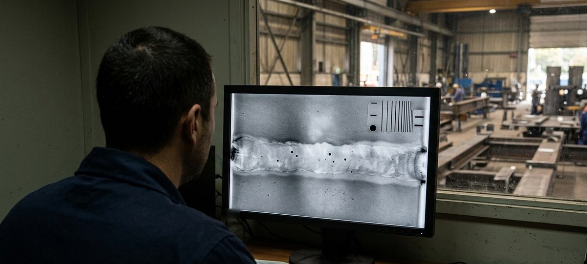
The last stretch is evaluation. It belongs to personnel certified at least to Level 2 for the method, who interpret the images against the acceptance level in the specification and write the report. A rejected joint goes back for repair and has to be radiographed again, and under progressive sampling a rejection extends testing to other joints. That is why the time estimate for a job should include a realistic repair rate, taken from the shop's own history.
What to send us for an assessment
To understand which solution fits your production we need a few data points:
- materials and thicknesses to be tested;
- joint diameters and geometry, including any internal access to the pipes;
- monthly volumes and how steady they are over the year;
- governing standard or code, required technique class or acceptance level;
- where testing takes place, in the shop or on site;
- current system or outside service in use, with the waiting times it causes you.
You can send them by email to info@dipitech.com or on WhatsApp, attaching a drawing of a typical joint and the relevant part of the specification if you have them. You can also use the contact form.
With this information we help you choose the radiographic system for your welds, from X-ray tube or generator to DR detector and systems customized to your application, or work out whether an outside service makes more sense. The available technologies are described on the dedicated industrial radiography page, and for field work you can also look at the portable X-ray generators we represent.
Request a quote
Leave your name, email, and a few lines about your application, with no obligation. We reply within 24 hours with initial technical guidance and a quote.
Frequently asked questions about weld radiography
When is weld radiography required?
When the product code, the execution standard or the contract calls for it. For pressure equipment, Directive 2014/68/EU ties the extent of testing to the joint coefficient; for piping to ASME B31.3, normal fluid service requires random examination of at least 5% of circumferential welds; in structural steelwork EN 1090-2 sets testing by execution class. The radiography standard specifies how to perform the test and leaves the decision on whether and how much to test to other documents.
Which standard applies to weld radiography?
For the technique, ISO 17636-1 with film and ISO 17636-2 with digital detectors, both from 2022. Sensitivity is demonstrated with the image quality indicators of the ISO 19232 series, while acceptance criteria are in ISO 10675-1 for steel, nickel and titanium and in part 2 for aluminum. ISO 17635:2025 guides the choice of method and ties these documents together.
What is the difference between class A and class B in ISO 17636?
Class A is the basic technique and class B the improved one, with stricter requirements on source-to-object distance, IQI sensitivity and number of exposures. The class follows from the quality level required for the joint: quality levels B and C of ISO 5817 lead to class B, level D to class A. In practice class B lengthens exposure and setup times.
Do you need a shielded room for weld radiography in the shop?
In the shop it is the recommended solution. The IAEA SSG-11 guide says to work in a shielded enclosure whenever reasonably practicable and to use field radiography only for parts that are fixed in place or too large or heavy to move. In Italy, shielding, classified areas and personnel categories are defined by the radiation protection expert under Legislative Decree 101/2020.
Who can perform and evaluate weld radiography?
Personnel qualified and certified for the radiographic method to ISO 9712 or an equivalent scheme. Level 1 performs exposures following written instructions, Level 2 sets up the technique, interprets the images and writes the report, and Level 3 approves procedures and techniques. For pressure equipment in categories III and IV, Directive 2014/68/EU also requires the personnel to be approved by a recognized third-party organization.
Is an in-house radiography system or an outside NDT service the better choice?
It depends on volumes, thicknesses and logistics. With joints to radiograph every week, movable parts and a thickness range covered by a single tube, an in-house system cuts waiting time and brings evaluation to the same day. With occasional campaigns, field work or thicknesses that call for gamma sources, an outside service avoids licensing and fixed costs. DIPITECH helps you make the comparison from your own data, with a reply within 24 hours.
How much does weld radiography cost?
There is no single price that fits every case, because cost depends on thicknesses, number of exposures per joint, technique class, location and detector type. When comparing an in-house system with an outside service, the fixed costs of radiation protection, personnel and periodic checks also count. Starting from material, diameters, thicknesses and volumes, DIPITECH prepares an assessment with a tailored quote within 24 hours.