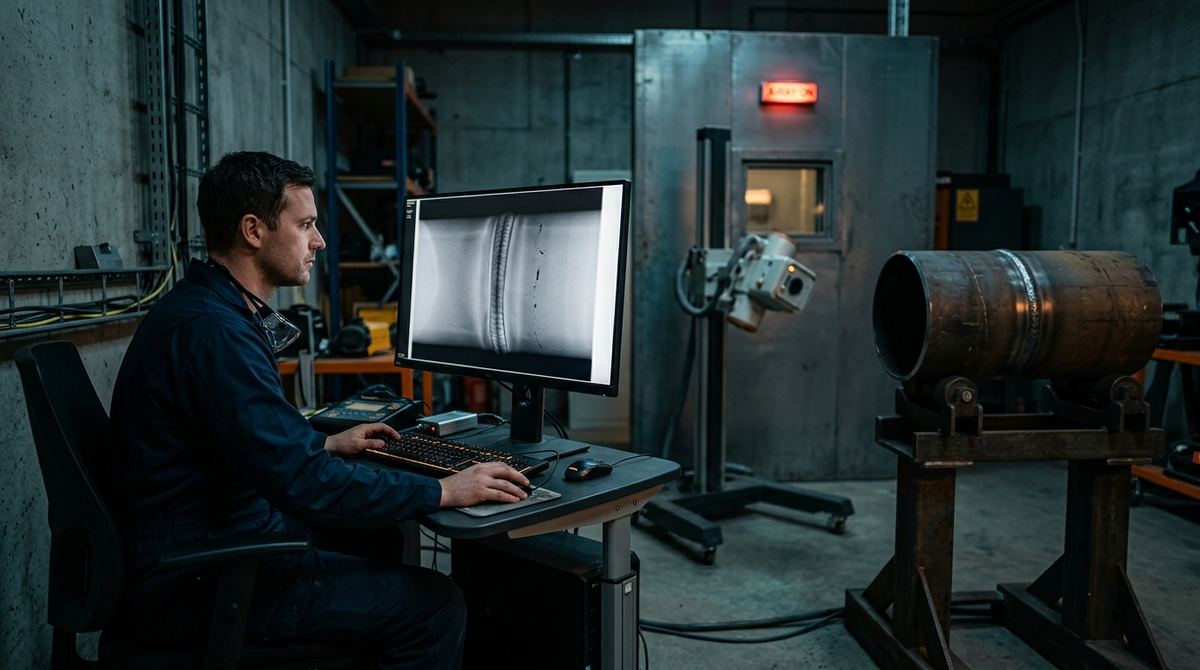
On the screen or on the film viewer, the same dark mark can be harmless porosity, a slag inclusion at the edge of acceptability or the start of a crack that condemns the joint. An industrial radiograph is a map of attenuation, and it has to be read with method. Before interpretation, though, comes technique: an image exposed with the wrong geometry or with a misplaced IQI proves nothing, however sharp it looks.
The three typical cases below start from the part. The first is weld radiography on pipe butt joints, the second covers sand and die castings, the third the exposure setup common to both. The choice between film, CR and DR has its own article, CR or DR in industrial radiography; here what matters is geometry, image quality indicators and how to read the defects.
Who decided the reject rate long before the radiograph
The letter that decides how many welds will be cut out is written by whoever drafts the specification, often without knowing what it costs, and it reaches the radiographer as a given. It is the ISO 5817 quality level, B, C or D, and everything else follows from that single letter. Tables 2 and 3 of ISO 10675-1:2021, one for film and one for digital detectors, then tie each level to an ISO 17636 technique class and an acceptance level. Quality level B goes with class B and acceptance level 1. Level C still takes class B and level 2, with a note allowing the minimum number of exposures of class A on circumferential welds. Level D takes class A, the basic one, and level 3. Asking for B or C therefore means paying for the improved technique, with longer distances and longer exposures, and only level D leaves the basic technique.
It helps to say what each of these standards does not do, because this is where specifications most often go wrong. ISO 17636 contains no acceptance criteria: Part 2, the digital one, says so in its own scope and points to the ISO 10675 series. The first tells you how to make the image and prove it is readable, the second what to reject. ISO 17635 guides the choice of method and techniques, and its 2025 edition warns that acceptance levels are not an automatic translation of quality levels. A purchase order that asks for "radiography to ISO 17636" and nothing else buys a picture without a verdict.
Well-written specifications then contain a detail worth whole contracts that almost no quotation mentions. Acceptance levels 2 and 3 can be specified with the suffix X, and then any indication longer than 25 mm is unacceptable, whatever the level's own calculations would allow. That suffix alone can swing the rework rate of a batch the other way. Whoever receives a specification should look for that X before quoting, and whoever writes it should know they are writing it.
For aluminum the pair changes: imperfection types and quality levels come from ISO 10042, acceptance levels from Part 2 of ISO 10675. Quoting ISO 5817 for a light-alloy joint is a frequent error in tender documents. Castings follow yet another route, by comparison with reference radiographs, which is the second case below. One element is common to all of them, the sensitivity achieved, which is demonstrated with the image quality indicators of the ISO 19232 series. The full chain, including steel fabrication under EN 1090-2 and class compensation in digital work, is in our article on who decides ISO 10675 acceptance levels.
First case: pipe weld radiography and exposure geometry
The typical scenario is girth welds on power-plant piping or a transmission line, with diameters from 25 to 400 mm, wall thicknesses from 3 to 20 mm and TIG, stick or wire welding. The first decision is the exposure geometry, which ISO 17636-1 groups into a few families and which depends mainly on where the source can go.
| Technique | When it is used | Joint coverage |
|---|---|---|
| Single wall, single image (SWSI), source at the center | Access to the center of the pipe, with a crawler in pipelines | One exposure for the whole circumference, with the beam crossing one wall |
| SWSI with internal detector | External source, internal access only for the detector | Several exposures by sector |
| Double wall, single image (DWSI) | Larger diameters, roughly above 100 mm, with no internal access | Only the detector-side wall is interpreted; at least three exposures at 120 degrees, often more |
| Double wall, double image (DWDI), elliptical | Small diameters, roughly up to 100 mm, and thin walls | Weld projected as an ellipse, both walls in one image; normally two exposures at 90 degrees |
| DWDI superimposed | When the ellipse does not open up, because the weld is wide for the diameter | At least three staggered exposures |
A source at the center is the best and most productive geometry, because the beam crosses a single wall almost perpendicularly; the panoramic tube that makes it possible is described in our article on focal spot and X-ray tube parameters. Where internal access is missing, double-wall work costs exposures, and their number around the circumference has to be calculated from diameter and thickness. Counting them wrong leaves sectors with excessive penetrated thickness, outside the required sensitivity.
The second decision is the image quality indicator, wire type to ISO 19232-1 or step-hole type to ISO 19232-2. As a rule it goes on the source side, on the base material next to the weld; when only the detector side is possible it must be marked, and the technique qualified accordingly. The ISO 17636 tables set the wire to be seen as a function of penetrated thickness and technique class, with class B more demanding than class A.
First case: how weld defects look on a radiograph
| Defect | Radiographic appearance | Interpretation key |
|---|---|---|
| Porosity | Sharp, rounded dark spots, isolated or grouped (clusters, alignments) | Regular shape; the distribution, uniform or aligned with the root, points to the cause |
| Slag inclusions | Irregular, elongated dark indications, often in line along the fusion faces between passes | Jagged outline; typical of covered electrode and submerged arc processes |
| Lack of fusion | Thin dark line offset toward the fusion face, often on one side, slightly wavy | Position on the bevel side; a planar defect, visible only if nearly parallel to the beam |
| Incomplete penetration | Continuous, straight dark line at the center of the weld, at the root | Follows the joint axis; sharp edges of the unfused faces |
| Cracks | Very fine dark lines, jagged or branched, sometimes barely visible | Planar defect: detectability collapses if the plane is not aligned with the beam |
| Undercut | Irregular dark band along the outer edge of the weld | Correlate with visual examination of the outer profile |
On the image the interpreter then applies the criterion set upstream. At acceptance level 2 of ISO 10675-1, the one that corresponds to ISO 5817 quality level C, porosity and slag are allowed within limits on size and sum. Cracks, by contrast, are not accepted at any of the three levels. Radiography's structural limit remains orientation, because a planar defect perpendicular to the beam can be invisible. That is why, on heavy sections and critical joints, radiography is paired with or replaced by ultrasonic testing, as our comparison of industrial radiography and ultrasonic testing explains.
Do you need to set up radiographic testing for your welds?
Send us diameters, wall thicknesses, material, applicable standard and volumes: we will recommend technique, source and detector, with a tailored quote within 24 hours and a test on your own material at no obligation.
Email us Message us on WhatsAppSecond case: sand and die castings and the logic of severity grades
The second scenario puts a sand-cast steel valve body and a die-cast aluminum automotive housing on the bench. The defects to look for change, and above all the way they are judged. Shrinkage is a solidification cavity with jagged outlines, concentrated, sponge-like or filamentary, that gathers in massive sections and thermal hot spots. Gas porosity instead gives rounded, sharp-edged indications, and it dominates in die castings, where fast die filling traps air. When housings are made by the thousand, inspection often moves in-line with industrial radioscopy, which looks at every part within the cycle time.
Sand or oxide inclusions look darker or lighter than the matrix depending on whether they are less or more dense than the metal. A cold shut shows as a dark line with rounded edges where two metal fronts met without fusing, a close relative of the misrun.
Unlike welds, castings have no universal level. Evaluation is done by comparison with reference radiographs that show each defect family at increasing severity grades. For light alloys the references are ASTM E155-20, for aluminum and magnesium sand and permanent-mold castings, and ASTM E505-22 for die castings in the same alloys. For steel the same ASTM family offers three catalogs split by thickness: E446-20(2026) up to 50.8 mm, E186-20(2026) from 50.8 to 114 mm and E280-21(2026) from 114 to 305 mm. The drawing or purchase specification sets the maximum acceptable grade, often by zone, strict on machined surfaces and pressure-retaining areas, more lenient in heavy sections. The general guide to radiographic quality on film remains ASTM E94/E94M-22. When the casting geometry makes the projection ambiguous, or porosity has to be measured in volume, the next step is computed tomography, covered in our industrial CT scanning guide.
Third case: setting up the exposure, from screens to IQIs
The third case runs across the first two. Voltage selection follows the rule of the lowest kV compatible with the thickness. Attenuation coefficients, the ISO 17636 curves and the geometric unsharpness calculations are in our article on X-ray tube focal spot and parameters. What remains here are the other elements that decide whether the image is valid.
With film, thin lead screens in contact intensify the image and filter scattered radiation; backscatter is controlled with rear shielding and checked with the classic lead letter B on the back of the cassette. Density in the area of interest must stay above a minimum, at least 2.0 in class A and 2.3 in class B under ISO 17636-1, with an upper limit tied to the viewer's luminance. Outside that range perceived contrast collapses and the report loses its value.
In digital work, CR or DR, the density criterion gives way to the normalized signal-to-noise ratio and correct use of the detector's dynamic range, with calibration and bad pixel correction. Basic spatial resolution is checked with the ISO 19232-5 duplex wire IQI, and panel selection criteria are in our article on how to choose a DR detector for weld inspection. In both worlds acceptability is judged only on a valid image, with a compliant technique, the IQI readable at the required value, density or SNR in range and full coverage of the joint. A technically invalid image has to be redone, and interpretation remains a disciplined comparison between indication and criterion.
The error that shows up in the timesheet, not in the report
The errors that invalidate a radiograph nearly all come from haste. Raising kV to go faster flattens contrast and makes fine porosity disappear. Cutting the number of exposures around a circumference leaves sectors outside the required sensitivity; forcing the elliptical technique on too large a diameter superimposes the two walls and makes interpretation questionable. None of the three shows on the finished image unless you know what to look for.
The most reliable indicator of a campaign's quality therefore often sits outside the image, in the ratio between declared joints and site hours. A number of exposures per shift that does not fit the setup times is a warning sign worth investigating before anyone looks at the films.
One limit remains that no procedure fixes. A report with no indications says that, with that technique and that beam orientation, nothing detectable emerged. For cracks, whose visibility depends on opening and orientation, the conclusion you can legitimately draw is narrower than the one clients tend to draw, which is why critical joints get a second method.
What to send us for an assessment
To set up or review radiographic testing of welds or castings we need these facts:
- part type: pipe (diameter and wall thickness), plate, sand or die casting;
- material or alloy, and minimum and maximum thicknesses to penetrate;
- access: whether the inside of the pipe can be reached or only the outside;
- applicable standard and required level (ISO 5817 or ISO 10042 quality level, severity grade for castings);
- defects of most concern: porosity, lack of fusion, cracks, shrinkage;
- source and detector currently in use, if any;
- volumes: joints or castings per day or per month.
You can send them by email to info@dipitech.com or on WhatsApp, with drawings, photos or a sample radiograph if you have them.
Setting up radiographic testing properly means bringing together standard, part geometry, source, detector and acceptance criterion, and it works best starting from your own joints and castings. If your case is close to one of those described, the next step is an application assessment on real samples. It leads to a tailored quote within 24 hours for industrial radiography systems, from generators to DR detectors, CR systems and accessories.
Frequently asked questions about weld and casting radiography
Which radiographic technique is used for small-diameter pipes?
Usually double wall, double image in elliptical projection, with the source tilted to the axis and normally two exposures at 90 degrees. The practical check is on the image: if the ellipse does not separate the two walls of the weld, you switch to the superimposed technique with at least three exposures, as ISO 17636-1 provides.
How do you tell lack of fusion from incomplete penetration on a radiograph?
By position: incomplete penetration runs straight along the center of the weld, at the root, while lack of fusion shifts toward the bevel face, often on one side only. Knowing the joint preparation and the process helps; when in doubt, confirmation comes from a second exposure at a different angle or from ultrasonic testing.
How do ISO 5817, ISO 17636 and ISO 10675-1 relate to each other?
ISO 5817 sets the quality level of the joint, B, C or D. The tables of ISO 10675-1:2021 link each one to an ISO 17636 technique class and an acceptance level: B with class B and level 1, C with class B and level 2, D with class A and level 3. ISO 17636 says how to make the image, ISO 10675-1 how to judge it, and whoever sets the letter in the specification also sets the cost of the examination.
Are casting radiographs evaluated like weld radiographs?
No. For castings the image is compared with reference radiographs at increasing severity grades, and the drawing sets the maximum grade for each zone. Two zones of the same casting can therefore have different criteria, and the report has to state which grade was applied where.
When does it make sense to move from film to digital CR or DR radiography?
When volumes, reporting times and film and chemistry costs grow together. The move does not change the required technique class or acceptance level: ISO 17636-2 asks the digital technique for sensitivity equivalent to film, checked with the same IQIs. The business case is made on cost per exposure.