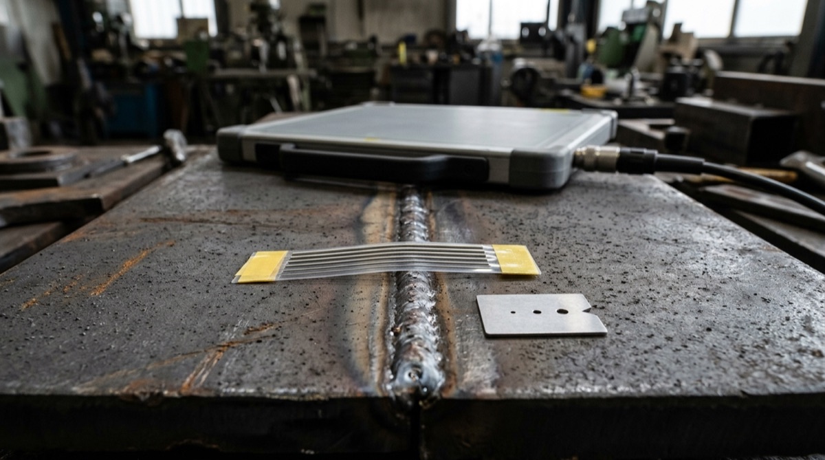
Every weld radiograph has to prove it saw enough, and it does so with the image quality indicator. The IQI, still called a penetrameter in many shops, is a plaque with calibrated holes or a row of wires of increasing diameter, made from the same material group as the part and laid on the joint during the exposure. If the required hole or wire shows on the image, the technique has the intended sensitivity. If it does not, the radiograph has to be retaken, whatever the weld looks like.
To choose the IQI, you enter the table of the governing standard with the thickness that standard prescribes. The tool does this for the two systems most often found in specifications, the ASME code with ASTM indicators and the ISO 17636 series with ISO 19232 indicators. The complete tables are further down, in case you prefer to look them up or need to quote them in a procedure.
Find the IQI for your thickness
Pick the set of standards in your specification. The result updates as you type.
What an IQI measures, and what it doesn't
An IQI measures contrast sensitivity, and to some extent image sharpness, under the conditions of that exposure: energy, source, distances, detector and film processing or image processing. It cannot tell you whether a tight crack tilted against the beam will show, because that depends on the opening and orientation of the flaw. That is why the standards treat it as a minimum technique requirement and not as a guarantee of detection. With digital detectors, contrast sensitivity alone is not enough, and ISO 17636-2 adds the duplex wire IQI of ISO 19232-5 to measure basic spatial resolution.
Holes or wires, two readings of the same sensitivity
The hole-type IQI of ASTM E1025 is a plaque of thickness T with three holes of diameter T, 2T and 4T. The number on it is the thickness in thousandths of an inch, so an IQI 20 is 0.020 in thick, about half a millimeter. The holes never go below 0.010, 0.020 and 0.040 in, even on the thinnest plaques. Quality is written as two numbers, and 2-2T means a plaque equal to 2% of the part thickness with the 2T hole visible.
The wire IQI of ASTM E747 holds six wires per set, in four sets from A to D, for 21 diameters from 0.08 to 8.13 mm. The standard treats it as equivalent to the 2-2T hole level between 6.4 and 152 mm of thickness. ISO 19232-1 indicators follow the same idea with 19 wires, from W1 at 3.2 mm to W19 at 0.05 mm, and here a higher number means a thinner wire. The diameters in the two systems are almost the same, so ASTM wire 8 at 0.41 mm is practically ISO W10 at 0.40 mm. The tables that say which wire you need, however, are different.
To compare different quality levels, use the equivalent penetrameter sensitivity, the EPS in the E1025 appendix: 100 divided by the part thickness, times the square root of T times H over 2. Run the numbers and you find that ASME Table T-276 does not apply 2% strictly. On 25 mm of steel, source side, it calls for IQI 25, which works out at about 2.5%, and on 3 mm it calls for IQI 12, about 10%. The tool calculates the EPS for every hole-type case, so you see right away how demanding the requirement really is. In aerospace practice, ASTM E1742 instead leaves the radiographic quality level among the items to agree with the customer's cognizant engineering organization.
Why the IQI goes on the source side
All the standards start from the same rule. The indicator sits on the side of the part facing the source, farthest from the detector, where its image gets the largest geometric unsharpness and represents the worst case for flaws within the thickness. On the detector side the same wire looks sharper and would give an overly optimistic sensitivity.
When the source side cannot be reached, as inside small-bore pipe, the IQI moves to the detector side with a lead letter F next to it. ASME compensates by asking for a more demanding indicator, and in Table T-276 the detector-side column is shifted by one step: between 12.7 and 19 mm, for example, you need IQI 17 instead of 20 and wire 7 instead of 8. For single-wall work, ISO 19232-3 rules out its tables on the detector side, and ISO 17636 requires the value to be established with a comparison exposure, with one IQI on each side under the same conditions. For double wall, ISO 19232-3 has tables written specifically for the detector side.
The thickness that goes into the table
Most errors start before the table is even opened. For ASME, the selection thickness is the nominal single-wall thickness plus the estimated weld reinforcement, cap and root, up to the maximum allowed by the referencing code. Backing rings and strips do not count, and even in double-wall techniques the table is entered with a single wall.
The ISO tables use the nominal thickness t for single wall and the penetrated thickness w for double wall, normally two walls. The same pipe with an 8 mm wall, in class B with the IQI on the source side, therefore needs W15 in single wall and W13 in double wall with a double image, where the thickness to penetrate doubles.
Mistakes that cost a reshoot
- The wrong material group is the most basic slip, and the rule is simple: you can use an IQI from a group that absorbs less than the part, such as a steel IQI on a nickel-chromium-iron alloy, never the other way around.
- A plaque often ends up on base metal next to a weld with reinforcement, with no shim under it. With film, ASME requires the density in the area of interest to stay within -15% and +30% of the density through the IQI; otherwise an additional IQI is needed.
- Wires laid parallel to the weld are useless, because they belong across the weld, perpendicular to its axis, so the essential wire sees the weld metal.
- The wrong set is a classic: wires 6, 11 and 16 belong to two sets, the others to one only, and if the essential wire is not in the set on the part, the check does not count.
- The source-side table gets used with a detector-side IQI, sometimes without the letter F. The value looks met, but the real sensitivity is lower.
- The gamma relaxation gets applied without a written agreement. With iridium-192 and selenium-75, ISO 19232-3 accepts one or two values less only in certain thickness ranges, and only if agreed between the parties.
Many of these problems are solved upstream, by choosing source, detector and geometry around the IQI value you need to reach. That is the subject of the guide on how to choose a DR detector for welds and of the one on X-ray tube focal spot. For the overall organization of testing, procedure and personnel included, see how to organize weld radiography, while testing class and acceptance level come from our ISO 5817 tool and the article on who decides acceptance levels. The possible setups, from portable tubes to custom systems, are collected on the industrial radiography page.
We help you choose the radiographic system and accessories
Send us thicknesses, material, technique and the standard in your specification: we help you work out which setup reaches the required IQI on your parts, with a reply within 24 hours.
Email us Message us on WhatsAppThe complete tables
The tables cover every case in the tool, in a form that works for an engineering office or for whoever writes a procedure. Sources are listed below the tables.
ASME V Table T-276: IQI selection by thickness
| Thickness (mm) | Inches | Source, hole IQI | Source, wire | Detector, hole IQI | Detector, wire |
|---|---|---|---|---|---|
| ≤ 6.4 | ≤ 0.25 | 12 | 5 | 10 | 4 |
| > 6.4–9.5 | > 0.25–0.375 | 15 | 6 | 12 | 5 |
| > 9.5–12.7 | > 0.375–0.50 | 17 | 7 | 15 | 6 |
| > 12.7–19.0 | > 0.50–0.75 | 20 | 8 | 17 | 7 |
| > 19.0–25.4 | > 0.75–1.00 | 25 | 9 | 20 | 8 |
| > 25.4–38.1 | > 1.00–1.50 | 30 | 10 | 25 | 9 |
| > 38.1–50.8 | > 1.50–2.00 | 35 | 11 | 30 | 10 |
| > 50.8–63.5 | > 2.00–2.50 | 40 | 12 | 35 | 11 |
| > 63.5–101.6 | > 2.50–4.00 | 50 | 13 | 40 | 12 |
| > 101.6–152.4 | > 4.00–6.00 | 60 | 14 | 50 | 13 |
| > 152.4–203.2 | > 6.00–8.00 | 80 | 16 | 60 | 14 |
| > 203.2–254.0 | > 8.00–10.00 | 100 | 17 | 80 | 16 |
| > 254.0–304.8 | > 10.00–12.00 | 120 | 18 | 100 | 17 |
| > 304.8–406.4 | > 12.00–16.00 | 160 | 20 | 120 | 18 |
| > 406.4–508.0 | > 16.00–20.00 | 200 | 21 | 160 | 20 |
The essential hole is always 2T. Selection thickness = nominal single wall plus estimated reinforcement, up to the referencing code maximum, backing rings excluded. Source: ASME BPVC Section V, Article 2, Table T-276, cross-checked against public technical reproductions.
ASTM E747: wires, diameters and sets
| Wire No. | Diameter (in) | Diameter (mm) | Set | Closest ISO 19232-1 wire |
|---|---|---|---|---|
| 1 | 0.0032 | 0.08 | A | W17 (0.08 mm) |
| 2 | 0.004 | 0.10 | A | W16 (0.10 mm) |
| 3 | 0.005 | 0.13 | A | W15 (0.125 mm) |
| 4 | 0.0063 | 0.16 | A | W14 (0.16 mm) |
| 5 | 0.008 | 0.20 | A | W13 (0.20 mm) |
| 6 | 0.010 | 0.25 | A or B | W12 (0.25 mm) |
| 7 | 0.013 | 0.33 | B | W11 (0.32 mm) |
| 8 | 0.016 | 0.41 | B | W10 (0.40 mm) |
| 9 | 0.020 | 0.51 | B | W9 (0.50 mm) |
| 10 | 0.025 | 0.64 | B | W8 (0.63 mm) |
| 11 | 0.032 | 0.81 | B or C | W7 (0.80 mm) |
| 12 | 0.040 | 1.02 | C | W6 (1.00 mm) |
| 13 | 0.050 | 1.27 | C | W5 (1.25 mm) |
| 14 | 0.063 | 1.60 | C | W4 (1.60 mm) |
| 15 | 0.080 | 2.03 | C | W3 (2.00 mm) |
| 16 | 0.100 | 2.54 | C or D | W2 (2.50 mm) |
| 17 | 0.126 | 3.20 | D | W1 (3.20 mm) |
| 18 | 0.160 | 4.06 | D | – |
| 19 | 0.200 | 5.08 | D | – |
| 20 | 0.250 | 6.35 | D | – |
| 21 | 0.320 | 8.13 | D | – |
Set A wires 1-6, set B 6-11, set C 11-16, set D 16-21 (ASTM E747 Table 1 and ASME V T-233.2). ISO diameters are the nominal ISO 19232-1 values: the match is numerical and does not make the selection tables interchangeable.
ASTM E1025: hole IQIs used by Table T-276
| IQI No. | Thickness T, in (mm) | 1T hole (in) | 2T hole (in) | 4T hole (in) |
|---|---|---|---|---|
| 10 | 0.010 (0.25) | 0.010 | 0.020 | 0.040 |
| 12 | 0.012 (0.30) | 0.012 | 0.024 | 0.048 |
| 15 | 0.015 (0.38) | 0.015 | 0.030 | 0.060 |
| 17 | 0.017 (0.43) | 0.017 | 0.034 | 0.068 |
| 20 | 0.020 (0.51) | 0.020 | 0.040 | 0.080 |
| 25 | 0.025 (0.64) | 0.025 | 0.050 | 0.100 |
| 30 | 0.030 (0.76) | 0.030 | 0.060 | 0.120 |
| 35 | 0.035 (0.89) | 0.035 | 0.070 | 0.140 |
| 40 | 0.040 (1.02) | 0.040 | 0.080 | 0.160 |
| 50 | 0.050 (1.27) | 0.050 | 0.100 | 0.200 |
| 60 | 0.060 (1.52) | 0.060 | 0.120 | 0.240 |
| 80 | 0.080 (2.03) | 0.080 | 0.160 | 0.320 |
| 100 | 0.100 (2.54) | 0.100 | 0.200 | 0.400 |
| 120 | 0.120 (3.05) | 0.120 | 0.240 | 0.480 |
| 160 | 0.160 (4.06) | 0.160 | 0.320 | 0.640 |
| 200 | 0.200 (5.08) | 0.200 | 0.400 | – |
Number = thickness in thousandths of an inch. Holes equal to T, 2T and 4T, never below 0.010, 0.020 and 0.040 in (ASTM E1025). No 4T hole is listed for IQI 200. Table T-276 always uses the 2T hole.
ASTM E747 and E1025 material groups
| Group | IQI material | Used on |
|---|---|---|
| 03 | magnesium | alloys with magnesium as the main constituent |
| 02 | aluminum | alloys with aluminum as the main constituent |
| 01 | titanium | alloys with titanium as the main constituent |
| 1 | carbon steel or 300 series stainless | carbon, low-alloy and stainless steels, manganese-nickel-aluminum bronze |
| 2 | aluminum bronze or nickel-aluminum bronze | all aluminum bronzes and nickel-aluminum bronzes |
| 3 | nickel-chromium-iron alloy (UNS N06600) | nickel-chromium-iron alloys and 18% nickel maraging steel |
| 4 | 70/30 nickel-copper or 70/30 copper-nickel alloy | nickel, copper, nickel-copper and copper-nickel alloys, all brasses |
| 5 | tin bronze | tin bronzes, valve bronze and leaded tin bronzes |
Absorption increases from 03 to 5. An IQI from one group can be used on a material from a later group, as long as the required quality level is maintained (ASTM E747 and E1025, Material Groups section).
ISO, single wall with IQI on the source side: wire IQIs
| Value | Wire diameter | Class A, nominal thickness t | Class B, nominal thickness t |
|---|---|---|---|
| W4 | 1.60 mm | over 250 mm | – |
| W5 | 1.25 mm | over 150 to 250 mm | over 350 mm |
| W6 | 1.00 mm | over 85 to 150 mm | over 200 to 350 mm |
| W7 | 0.80 mm | over 55 to 85 mm | over 120 to 200 mm |
| W8 | 0.63 mm | over 40 to 55 mm | over 65 to 120 mm |
| W9 | 0.50 mm | over 32 to 40 mm | over 45 to 65 mm |
| W10 | 0.40 mm | over 25 to 32 mm | over 35 to 45 mm |
| W11 | 0.32 mm | over 15 to 25 mm | over 30 to 35 mm |
| W12 | 0.25 mm | over 10 to 15 mm | over 20 to 30 mm |
| W13 | 0.20 mm | over 7 to 10 mm | over 12 to 20 mm |
| W14 | 0.16 mm | over 5 to 7 mm | over 8 to 12 mm |
| W15 | 0.125 mm | over 3.5 to 5 mm | over 6 to 8 mm |
| W16 | 0.10 mm | over 2 to 3.5 mm | over 4 to 6 mm |
| W17 | 0.08 mm | over 1.2 to 2 mm | over 2.5 to 4 mm |
| W18 | 0.063 mm | up to 1.2 mm | over 1.5 to 2.5 mm |
| W19 | 0.05 mm | – | up to 1.5 mm |
ISO, single wall with IQI on the source side: step/hole IQIs
| Value | Class A, nominal thickness t | Class B, nominal thickness t |
|---|---|---|
| H2 | – | up to 2.5 mm |
| H3 | up to 2 mm | over 2.5 to 4 mm |
| H4 | over 2 to 3.5 mm | over 4 to 8 mm |
| H5 | over 3.5 to 6 mm | over 8 to 12 mm |
| H6 | over 6 to 10 mm | over 12 to 20 mm |
| H7 | over 10 to 15 mm | over 20 to 30 mm |
| H8 | over 15 to 24 mm | over 30 to 40 mm |
| H9 | over 24 to 30 mm | over 40 to 60 mm |
| H10 | over 30 to 40 mm | over 60 to 80 mm |
| H11 | over 40 to 60 mm | over 80 to 100 mm |
| H12 | over 60 to 100 mm | over 100 to 150 mm |
| H13 | over 100 to 150 mm | over 150 to 200 mm |
| H14 | over 150 to 200 mm | over 200 to 250 mm |
| H15 | over 200 to 250 mm | – |
| H16 | over 250 to 320 mm | – |
| H17 | over 320 to 400 mm | – |
| H18 | over 400 mm | – |
Source: ISO 19232-3:2013, Tables 1-4 (public preview), the same values as Annex B of ISO 17636-1 and ISO 17636-2. For class B with step/hole IQIs the table stops at 250 mm. These tables do not apply with the IQI on the detector side.
ISO, double wall: wire IQIs
| Value | Wire diameter | Double image, source side, class A (w) | Double image, source side, class B (w) | Detector side, class A (w) | Detector side, class B (w) |
|---|---|---|---|---|---|
| W3 | 2.00 mm | over 380 mm | – | – | – |
| W4 | 1.60 mm | over 220 to 380 mm | – | over 375 mm | – |
| W5 | 1.25 mm | over 120 to 220 mm | over 250 mm | over 225 to 375 mm | – |
| W6 | 1.00 mm | over 85 to 120 mm | over 170 to 250 mm | over 125 to 225 mm | over 300 mm |
| W7 | 0.80 mm | over 60 to 85 mm | over 100 to 170 mm | over 85 to 125 mm | over 180 to 300 mm |
| W8 | 0.63 mm | over 50 to 60 mm | over 70 to 100 mm | over 60 to 85 mm | over 100 to 180 mm |
| W9 | 0.50 mm | over 40 to 50 mm | over 55 to 70 mm | over 48 to 60 mm | over 70 to 100 mm |
| W10 | 0.40 mm | over 30 to 40 mm | over 45 to 55 mm | over 38 to 48 mm | over 55 to 70 mm |
| W11 | 0.32 mm | over 18 to 30 mm | over 38 to 45 mm | over 22 to 38 mm | over 45 to 55 mm |
| W12 | 0.25 mm | over 12 to 18 mm | over 25 to 38 mm | over 15 to 22 mm | over 30 to 45 mm |
| W13 | 0.20 mm | over 7 to 12 mm | over 15 to 25 mm | over 10 to 15 mm | over 18 to 30 mm |
| W14 | 0.16 mm | over 5 to 7 mm | over 8 to 15 mm | over 5 to 10 mm | over 12 to 18 mm |
| W15 | 0.125 mm | over 3.5 to 5 mm | over 6 to 8 mm | over 3.5 to 5 mm | over 6 to 12 mm |
| W16 | 0.10 mm | over 2 to 3.5 mm | over 4 to 6 mm | over 2 to 3.5 mm | over 4 to 6 mm |
| W17 | 0.08 mm | over 1.2 to 2 mm | over 2.5 to 4 mm | over 1.2 to 2 mm | over 2.5 to 4 mm |
| W18 | 0.063 mm | up to 1.2 mm | over 1.5 to 2.5 mm | up to 1.2 mm | over 1.5 to 2.5 mm |
| W19 | 0.05 mm | – | up to 1.5 mm | – | up to 1.5 mm |
w = penetrated thickness, normally 2t. The detector-side columns apply to double wall with single or double image. Values of ISO 19232-3:2013, reproduced in DNV Classification Notes No. 7 (2012), Tables 5-4 to 5-7. Step/hole values for double wall are not given.
What to send us for an assessment
If the result raises a real issue, for example a wire your current setup cannot show, a few details are enough for us to assess it:
- the standard called up in the specification (ASME V, ISO 17636 or other) and the testing class;
- material, wall thicknesses and joint diameters;
- exposure technique, single wall or double wall;
- the source and detector you use today, film, CR or digital detector;
- the required IQI and the value you reach today;
- volumes, in exposures per month.
You can send them by email to info@dipitech.com or on WhatsApp, with a sample radiograph if you can, or use the contact form.
Cite or link to this tool
If you work in an engineering office, teach at an NDT school or often answer questions in industry forums, you can link to the tool from your pages or course notes. The code below is ready to paste.
Frequently asked questions about IQIs
What is an IQI in radiography, and why is it also called a penetrameter?
An IQI, or image quality indicator, is a reference object radiographed together with the part to prove the sensitivity of the technique. It can be a plaque with calibrated holes or a series of wires of increasing diameter, made from the same material group as the part. The name penetrameter comes from early American standards and is still common in the shop. If the required hole or wire does not show on the image, the radiograph is not valid.
How do you select the IQI with ASME Section V Table T-276?
Start from the nominal single-wall thickness plus the estimated weld reinforcement, up to the maximum allowed by the referencing code and without counting backing rings. With that thickness, Table T-276 gives the hole IQI with the essential 2T hole or the essential wire, in two columns for source side and detector side. Between 12.7 and 19 mm, for example, the source side calls for IQI 20 or wire 8.
What is the difference between ASTM E1025 hole IQIs and ASTM E747 wire IQIs?
What changes is the element you have to see. A hole IQI is a plaque of thickness T with holes of T, 2T and 4T, and the number on it is the thickness in thousandths of an inch. A wire IQI has six wires per set, in four sets from A to D, for 21 diameters from 0.08 to 8.13 mm. ASTM E747 treats the wire as equivalent to the 2-2T hole level between 6.4 and 152 mm of thickness. Wires lie across the weld, while a plaque on base metal often needs a shim.
What does 2-2T sensitivity mean?
It is the most common quality level with hole IQIs. The first 2 means the plaque is 2% of the part thickness, and 2T means the visible hole has twice the plaque thickness as its diameter. ASTM E1025 links it to an equivalent sensitivity of 2%, while 2-1T is 1.4% and 2-4T is 2.8%. ASME Table T-276 does not apply 2% strictly, and on thin sections the actual sensitivity is coarser.
Should the IQI go on the source side or the detector side?
As a rule on the side of the part facing the source, farthest from the detector, where the IQI image represents the worst case. The detector side is used only if the source side cannot be reached, with a lead letter F next to the IQI. ASME has a dedicated column with a more demanding indicator. For single wall, the ISO tables do not apply on the detector side and ISO 17636 calls for a comparison exposure, while for double wall ISO 19232-3 has tables written for that position.
What IQI value does ISO 17636 require for class A and class B?
It depends on class, technique, IQI position and thickness. For single wall with the IQI on the source side, on 10 mm of steel class A calls for W13 and class B for W14, that is wires of 0.20 and 0.16 mm. With step/hole IQIs you need H6 in class A and H5 in class B. The minimum values are those of ISO 19232-3, which appear in Annex B of ISO 17636-1 and ISO 17636-2.