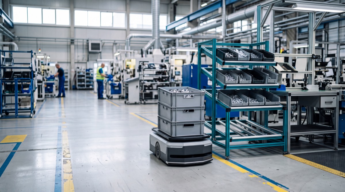
On many assembly lines, the first sign that in-plant logistics is falling behind is an operator standing still with empty hands. The bracket bin is empty. The full one is still in the supermarket, 120 meters away, and the coworker who runs the cart loop is on the other side of the building returning empties. The stoppage lasts four minutes and nobody logs it as a breakdown. Added up over two shifts and a dozen workstations, though, it lands straight in the line's OEE, under availability. This is usually where the idea of handing the loop to autonomous mobile robots (AMRs) begins: vehicles that navigate without floor guides and replan their route when they meet an obstacle.
The term milk run comes from external logistics. The Lean Enterprise Institute's Lean Lexicon defines it as a way to speed the flow of materials by routing vehicles to make multiple pickups and drop-offs on one loop, and notes that inside a plant the concept is similar to internal material handling routes. On the shop floor, a milk run is a fixed-interval loop that starts at the supermarket, the stock area close to the lines, delivers full containers to the points of use and picks up the empties. Alongside the classic loop, AMRs typically handle four other missions: on-call replenishment of the line side, delivery of kits prepared for a single assembly, transport of work in progress (WIP) between departments, and pickup of empties and scrap. Each has a different load profile. A project that treats them all the same gets the robot count wrong.
Demand is worked out backward, from part consumed to mission
You can't read the number of robots off a vehicle datasheet. It comes from line consumption, working back from the part to the container and from the container to the mission. Step one is the hourly demand for each line-side part number: the line rate multiplied by the quantity of that part used in one assembly. Step two is container capacity, which turns parts per hour into containers per hour. Step three is how many containers the robot carries per loop, and that gives the minimum milk run frequency.
An example. A line with a 90-second takt time builds 40 assemblies an hour. A bracket used twice per assembly is consumed at 80 parts an hour, and if the container holds 40, the station needs a full one every half hour. Repeating the calculation for the line's twelve part numbers, with one to four parts per assembly and containers holding 20 to 120 parts, the example comes to 15 full containers an hour to deliver and as many empties to collect. With a robot that carries four containers per loop, you need at least 3.75 loops an hour, which rounds up to four, one every fifteen minutes.
Container choice matters more than it seems. Doubling capacity halves the missions, but it also doubles line-side space and the capital tied up in stock. Battini, Faccio, Persona and Sgarbossa studied exactly this trade-off in the International Journal of Production Economics (2009). Their model compares assembly line feeding policies, from direct line-side supply to kitting, on handling cost, space and inventory. With kitting, the robot brings a cart holding all the parts for one or a few assemblies, already picked in the supermarket. That frees line-side space and cuts picking errors. It also moves work upstream, where someone has to build the kits, and it changes the mission profile: fewer containers, more carts, and a pace tied to the production sequence.
Mission cycle time, item by item
A mission's cycle time adds up four items: route length divided by average speed, load and unload times at stations, waits at intersections and doors, and an allowance for the unexpected. Speed is the most underestimated item, because the datasheet figure is a maximum, while on the floor the robot slows down in curves, near people and in zones where the risk assessment requires reduced speed. The example uses an effective average of 0.8 m/s, a working assumption to be confirmed with a layout simulation or a trial on the real route.
| Item | Example assumption | Seconds |
|---|---|---|
| Loop route (supermarket, 4 stops, return) | 420 m at 0.8 m/s | 525 |
| Loading at the supermarket | docking 20 s, transfer of 4 full and 4 empty containers 60 s | 80 |
| Line-side stops | 4 × (docking 20 s + full/empty swap 30 s) | 200 |
| Waits and intersections | about 10% of travel time | 55 |
| Milk run loop | total | 860 (14.3 min) |
| WIP mission, washing to assembly | 2 × 180 m at 0.8 m/s, hitch and unhitch 2 × 40 s, waits 45 s | 575 |
With these times, the math takes a few lines. The milk run needs four 860-second loops, or 3,440 seconds of work every hour. Moving WIP from washing to assembly adds three 575-second missions, another 1,725, for a total load of 5,165 seconds an hour. The robot count comes from dividing that load by the 3,600 seconds in an hour, by robot availability, and by the utilization factor you want to keep as a margin.
N robots = (missions/hour × cycle time in s) / (3,600 × availability × utilization factor)
In the example, availability is 0.90, the product of 95% technical availability and 95% of time not lost to charging, and the utilization factor is set at 0.85. The result is 5,165 / (3,600 × 0.90 × 0.85) = 1.88, so two robots, each busy for about 80% of available time. The milk run alone would have given 1.25, and again two robots, with the second idle for much of the shift. Pooling flows on a single fleet is often what puts the second vehicle to real use.
The utilization factor separates a project that holds up from one that breaks on the first bad day. Queueing theory explains why. As utilization approaches 100%, waiting times grow far faster than the load, and a robot running at 95% has no room for a late mission or a blocked intersection. If the example's peak hour runs 20% above average, the load rises to 6,198 seconds and the two robots work 96% of available time. In that hour the line starts waiting for parts. There are three ways out: a third robot, larger containers for high-usage parts, or a supermarket closer to the line. The method for finding the worst hour in your movement history is described in the article on evaluating an autonomous forklift and AMR project, where it's applied to a pallet warehouse. Which robot takes which mission, and when it goes to charge, is the subject of the review by Fragapane, de Koster, Sgarbossa and Strandhagen in the European Journal of Operational Research (2021). It organizes AMR planning and control in intralogistics into levels.
Charging needs its own check. With opportunity charging, the robot connects to the contacts while it waits for loading at the supermarket or between loops, and the example's 95% of usable time depends on those pauses existing. A robot running at 96% has none. Its battery drains loop after loop until it needs a long stop at the worst possible moment. The balance between energy used and charging minutes available is covered in the article on sizing charging stations.
Line-side stock has to cover the loop, plus the delay
A fixed-interval milk run works only if line-side stock covers the gap between two visits, plus one loop, plus the longest delay you decide to accept. For the example's bracket, with a visit every 15 minutes, a loop of about 15 and an allowed delay of 10, the station has to last 40 minutes of consumption, or 53 parts. Two containers of 40, one in use and one in reserve, are enough, the same two-bin scheme many lines already use with manual kanban. With 20-part containers you would need three, and the gravity flow rack would have to be redesigned.
The signal that triggers a mission also changes how the system behaves. In a fixed-interval loop, the robot comes by anyway and delivers whatever was consumed since the last visit. In on-call replenishment, the mission starts when the empty is placed on the return conveyor, when a rack sensor detects an open slot, or when the MES records consumption. The fixed loop is more predictable and easier to load evenly. On-call supply cuts stock, but it makes the load irregular. Many plants keep the fixed loop for steady-usage parts and on-call supply for irregular or bulky ones, and the robot count has to be based on the sum of both flows.
Want to know how many robots your lines need?
Send us your line rates, containers, distances and shifts. We'll tell you how many missions an hour your plant generates and whether an AMR milk run holds up at peak hour as well. A feasibility study on your data, with a tailored quote within 24 hours.
Email us Message us on WhatsAppConveyors, lifts or towing: the interface sets the length of each stop
At every stop the robot has to swap a full container for an empty one, and how it does that weighs on cycle time as much as the route does. A roller top module transfers containers to and from roller or gravity racks with no one touching them. It works well with standard containers, provided the line-side conveyor height is fixed and the robot always docks at the same point. Docking repeatability is measured with statistical methods such as those in ASTM F3499-21 on autonomous vehicle docking, and it's worth asking for it measured at your station rather than quoted from a catalog.
A lift module works differently. The robot slides under a cart, raises it a few centimeters, carries it to its destination, sets it down and leaves. It's the most flexible option for kits and WIP, because one robot can serve different carts, as long as they are designed with the right clearance, casters and frame. The limit is one cart per robot at a time.
Towing carries more per loop. A tugger robot hitches two, three or four carts and pulls them around the loop like a small train, and in automotive, supermarkets served by tow trains have spread precisely to feed mixed-model lines. Emde and Boysen (European Journal of Operational Research, 2012) handled the assignment of stations to loops and train departure times in a single model, two decisions that depend on each other. A train has a layout cost, though. It takes up more aisle, its carts cut corners unless they have coupled steering, and hitching and unhitching are often manual. Automatic hitches exist and take the operator out of the cycle, but they have to be checked on every cart type used in the plant.
Vehicle families, from platform robots to tuggers and autonomous pallet forklifts, are described on the page about AMR robots and autonomous forklifts. When the robot also needs an arm to pick parts, the project changes character, as explained in the article on mobile manipulators.
From the MES to the robot: who launches the mission, and over which protocol
An AMR feeding a line gets its orders from fleet management software, which in turn has to know what is needed and where. The reference model for this chain is the IEC 62264 series, the international version of ISA-95. It separates the manufacturing operations management level, where the MES and WMS sit, from the process control level. In a real project, that means deciding which system creates the request and which one turns it into a mission. It may be the MES, which knows the sequence, the WMS, which knows the supermarket locations, or a simple button on the line. Leave that choice implicit, and sooner or later the robot gets two orders for the same container, or none.
Between fleet manager and vehicles, the reference specification in Europe is VDA 5050, published by VDA and VDMA, which standardizes how orders and status are exchanged between a central controller and mobile robots. Version 3.0.0 came out in March 2026. It remains a communication interface. It doesn't certify safety and doesn't cover the link between the MES and the fleet manager. Requiring it in the specification lets vehicles from different manufacturers run under one controller, which helps when the milk run goes to platform robots and pallet moves go to autonomous forklifts.
The standards that matter, and the ones cited by mistake
An AMR running between lines is a driverless industrial truck, and its safety follows the standards for that family. These are the main ones to write into the specification.
- EN ISO 3691-4:2023, driverless industrial trucks and their systems: safety requirements and verification, with Annex A on preparing operating zones.
- EN ISO 13849-1:2023, safety-related parts of control systems: defines the Performance Levels used to implement functions such as personnel detection and speed control.
- ISO 12100:2010, risk assessment and risk reduction for the whole system, docking stations included.
- ANSI/A3 R15.08-1-2020 (reaffirmed in 2026) and R15.08-2-2023, the U.S. reference for industrial mobile robots and their integration into systems and applications.
- ISO 10218-2:2025, only if the robot carries an arm: it incorporates much of ISO/TS 15066 on collaborative applications.
- Regulation (EU) 2023/1230, which replaces the Machinery Directive from January 20, 2027.
Two standards often show up in specifications for no reason. ISO 13482:2014 covers personal care robots, such as mobile servant robots and person carriers, and explicitly excludes industrial robots, which it refers to ISO 10218. The revision now underway, which extends it to professional service robots, also leaves out industrial applications. It isn't relevant to a factory AMR. EN 1525 on driverless trucks is a legacy standard, replaced by EN ISO 3691-4, and a specification that still cites it was copied from an old document.
The sensitive point in line feeding is the stops. While docking, the robot gets closer to the line-side racks than its travel protective fields allow, and meanwhile the operator is picking a few steps away. Those moments need separate analysis in the risk assessment, with permitted speeds, reduced fields and any fixed guards on the side of the rack. The weight of safety on the overall project is covered in the article on AMR safety.
Before the robot come aisles, floors and forklift crossings
Along the path, ISO 3691-4 requires a clear space at least 0.5 m wide and 2.1 m high on both sides, measured to fixed structures. Where that clearance is missing, the area has to be designated and marked as an operating hazard zone, with reduced speed and additional warnings, and every slow section on the busiest route eats into loops. Near the lines, clearance is often the first thing to go, because the space between line-side racks and the aisle is contested by operators, manual carts and changeovers. Measure it before estimating cycle time.
Production floors differ from warehouse floors. Expansion joints, rapid-door thresholds, drain grates, oil and chips around machine tools all test wheels and sensors, and step, gap and slope limits have to be checked against the manufacturer's datasheet section by section. Forklift crossings need just as much attention. A robot 40 centimeters tall behind a pallet a meter and a half high is invisible from the driver's seat, and right-of-way rules should be written and marked on the floor before startup. Wireless coverage also has to be checked over the whole loop, because a dead spot in front of a door becomes a stoppage.
OEE, starved-line stoppages and labor hours freed, before and after
The result of a robotic milk run shows up on the line before it shows up on the robot. ISO 22400-2:2014 defines the OEE index as the product of availability, effectiveness and quality rate, and stoppages for missing material fall under availability. Measure that item first, in minutes per shift and per station, for two or three weeks before startup and with the same method afterward.
Alongside OEE, you need indicators for the transport system itself: missions late against the loop schedule, hourly utilization of each robot, missions canceled or relaunched by hand, and manual handling hours before and after. Count those hours for whoever actually ran the loop, because the material handler often also did checks, sequencing or small repairs that still have to be done. How to turn these numbers into an economic return is covered in the analysis of ROI, TCO and payback.
Mistakes that surface after acceptance testing
The classic case is a fleet sized on the average hour, which holds for weeks and gives way on the peak day. Forgetting the empties is subtler. If the robot delivers full containers but empties pile up at the line, within one shift the return conveyor is full and stops get longer, because the operator has to clear the slot by hand. The same goes for datasheet speed used in the calculation, already discussed under cycle time.
The last two mistakes are organizational. One is leaving the line-side racks as they were, designed for an operator reaching in rather than for a conveyor that has to find the same height every time. The other is never deciding who owns the call signal. MES, WMS and line buttons then launch missions in parallel, and the fleet chases duplicate requests.
When a robotic milk run doesn't pay off
In some situations a robot isn't the right answer. With a handful of containers a day, it would sit idle most of the time, and an operator who runs the loop alongside other tasks costs less. With the supermarket a few meters from the line, a fixed conveyor or a pass-through gravity rack solves the problem without vehicles. Heavy loads or full pallets call for other machines, as explained in the article on automating pallet handling in a running warehouse. Badly worn floors, steep ramps or outdoor routes need a case-by-case check, and sometimes that check ends the project.
The flip side is just as clear. Lines with a steady rate over two or three shifts, many line-side part numbers, distances of a few hundred meters and a material handler who spends the shift pushing carts make up the profile where an AMR milk run pays back best. Available technologies are described on the page about industrial automation and material handling robotics. The right robot comes after the mission count, never before, and if you haven't done that count yet, the next step is to run it on your own numbers.
What to send us for an assessment
To estimate how many missions an hour your plant generates and how many robots it needs, peak hour included, we need the following data, most of which you already have:
- a dimensioned layout of the area, with supermarket, lines, aisles, doors, slopes and forklift crossings;
- line rates or parts per hour, shifts worked and peak hours;
- a list of line-side part numbers with usage per assembly, container type and capacity;
- distances between supermarket, lines and departments, plus WIP, empty and scrap flows;
- current line-side interfaces (gravity racks, conveyors, carts) and working heights;
- systems in use (MES, WMS, ERP) and how material requests are created today.
You can send them by email to info@dipitech.com or on WhatsApp, with a few photos of the line side and the supermarket.
Request a quote
Leave your name, email, and a few lines about your application, with no obligation. We reply within 24 hours with initial technical guidance and a quote.
Frequently asked questions about AMRs for line feeding
How many AMR robots does it take to feed a production line?
The number comes from the mission load: missions per hour times cycle time in seconds, divided by 3,600, by robot availability and by a utilization factor that leaves a margin, usually around 0.8 to 0.85. Run the calculation on the peak hour and on the sum of all flows, including milk run, WIP and empties, not on the shift average.
What is an AMR milk run?
It's a fixed-interval loop in which an autonomous mobile robot leaves the supermarket, delivers full containers to the line's points of use and collects the empties. Compared with a manual loop, the robot keeps a repeatable schedule and frees up the material handler. Line-side stock has to cover the gap between two visits, the loop time and the longest delay you accept.
Is an AMR with a conveyor, a cart lift or a tugger the better choice?
It depends on what is swapped at each stop. A conveyor top transfers standard containers without an operator but needs fixed heights and repeatable docking. A lift module carries one cart at a time and is the most flexible for kits and WIP. A tugger carries more per loop, but it takes more aisle space and often needs manual hitching and unhitching.
Which standards apply to AMRs that feed production lines?
The reference standard is EN ISO 3691-4:2023 for driverless industrial trucks, with EN ISO 13849-1:2023 for safety functions and ISO 12100 for risk assessment. In the United States, the ANSI/A3 R15.08 series applies. ISO 10218-2:2025 comes in only if the robot carries an arm, while ISO 13482 covers personal care robots and isn't relevant. Regulation (EU) 2023/1230 applies from January 20, 2027.
Can AMRs talk to an MES and a WMS?
Yes, through fleet management software that receives requests from the MES, the WMS or line buttons and turns them into missions. Decide explicitly which system creates the request, to avoid duplicate orders. Between fleet manager and vehicles, the open reference specification is VDA 5050 from VDA and VDMA, which reached version 3.0.0 in March 2026.
How do I request a feasibility study from DIPITECH?
Send the area layout, line rates, the list of line-side part numbers with their containers, distances, shifts and current interfaces by email to info@dipitech.com, on WhatsApp or through the contact form. DIPITECH calculates missions and fleet size on your data and helps you choose the configuration. The tailored quote arrives within 24 hours.