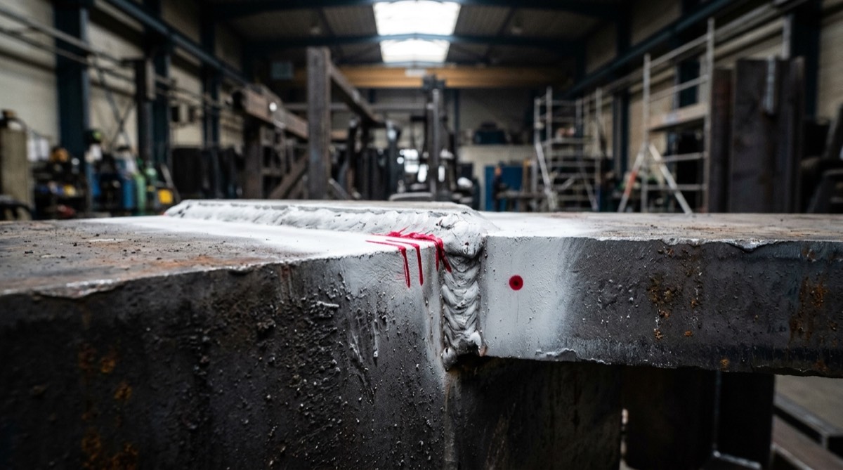
In structural steel fabrication, boiler and pressure vessel shops and maintenance workshops, liquid penetrant testing is often the first NDT method a weld meets after visual testing. The method is cheap, runs on three aerosol cans with no power supply, and works on austenitic stainless steel, aluminum, nickel alloys and titanium, where magnetic particle testing can't be used. That same simplicity makes it the method where a wrong result is easiest to get, because sensitivity depends almost entirely on execution: cleaning, temperature, timing, excess removal and lighting.
The references are the ISO 3452 series for the method and ISO 23277 for weld acceptance, both adopted in Europe as EN ISO standards. From there it is a short step to the practical choices a quality or welding coordinator has to make: which materials to use, how to write the procedure, when penetrant testing of welds is enough and when another method is needed.
What penetrant testing sees and what it misses
The principle is capillary action. A low surface tension liquid, dyed red or loaded with a fluorescent pigment, is spread over the clean surface and enters open discontinuities. Once the excess is removed, a thin developer layer draws the liquid trapped in the cavity back to the surface and forms an indication much wider than the flaw, so it can be seen with the naked eye. ISO 3452-1 lists what the method finds, namely cracks, laps, folds, porosity and lack of fusion, as long as they break the surface. Metals are the main field, but the standard also allows ceramics and other materials that are inert to the products and not excessively porous.
The same principle explains the limits, which are worth having clear before signing a procedure. A closed flaw, even a few tenths of a millimeter below the surface, gives no indication. A crack held shut by compressive stress, or covered by metal smeared during grinding, stays invisible. The indication shows where the flaw is and how long it is at the surface, but not how deep it goes, and ISO 23277 points out that the shape and size of an indication do not match those of the imperfection causing it. On porous materials, finally, the whole background takes the dye and the test loses its meaning.
The six-step procedure and the parameters the standard sets
The ISO 3452-1 sequence never changes: preparation and precleaning, penetrant application, excess penetrant removal, developer application, inspection with recording, and postcleaning. The standard requires an approved written procedure and requires the products, the test surface and the surroundings to stay between 10 and 50 °C. Outside that range, products and procedures qualified to ISO 3452-5 above 50 °C or ISO 3452-6 below 10 °C are needed. On a winter construction site or a line that has just been shut down, it is the first parameter to go wrong.
| Step | What is done | Parameter to set in the procedure |
|---|---|---|
| 1. Preparation and precleaning | Removal of slag, oxides, paint and oil, degreasing, thorough drying | Discontinuities free of residue; after blasting or grinding, consider etching |
| 2. Penetrant | Spraying, brushing or dipping, with the surface kept wet | Dwell time between 5 and 60 min, never below the manufacturer's minimum |
| 3. Excess removal | Dry cloth, then a cloth moistened with solvent (method C), or water washing (methods A, B, D) | Solvent never sprayed directly onto the part unless the technique is approved |
| 4. Developer | Thin, even layer applied right after drying | Development time typically between 10 and 30 min |
| 5. Inspection | First look right away, final evaluation at the end of development | Viewing conditions to ISO 3059 |
| 6. Recording and postcleaning | Description, sketch or photo of indications, removal of residues | Report with penetrant system designation and batch number |
Half of the result depends on preparation. Brushing, blasting and grinding take dirt off the surface, but they can smear metal over cracks and close them. That is why the standard requires checking that discontinuities stay open and, when needed, etching followed by rinsing. Pickling residues must also be removed, because acids and chromates sharply reduce the color and fluorescence of the penetrant. Drying has to be complete, since water or solvent left in a crack takes up the space the penetrant should fill.
Penetrant dwell time runs from 5 to 60 minutes and can't drop below the time the manufacturer recommends for the required sensitivity. Excess removal, on the other hand, is the step where most mistakes happen. With solvent-removable products, the ones in aerosol kits, a clean, dry, lint-free cloth goes first, followed by a cloth lightly moistened with solvent. Spraying solvent straight onto the weld is faster, yet it washes penetrant out of the cracks too, and the standard allows it only as a technically approved technique agreed between the parties.
Developer should go on as a thin, even layer, because a thick coat hides small indications instead of bringing them out. For development the standard gives 10 to 30 minutes, with a first look right after application that helps interpret indications before they spread. Experimental work published in Archives of Metallurgy and Materials shows how much the real development time depends on material, roughness and discontinuity width, with longer times on nickel alloys and rough surfaces than on structural steel. This is why ISO 23277 calls for the final evaluation after the minimum development time and before the indication degrades.
The order of testing matters as well. When other NDT methods are planned on the same part, ISO 3452-1 asks for penetrant testing to be done first, unless otherwise agreed, so that no contaminants are carried into open discontinuities.
Fluorescent or color contrast penetrants: sensitivity, lighting and environment
In ISO 3452-2 penetrants fall into three types: Type I fluorescent, Type II color contrast, the familiar red on white developer, and Type III dual purpose. A capital letter gives the removal method, A for water-washable, B and D for lipophilic and hydrophilic post-emulsifiable, C for solvent-removable, E for water- and solvent-removable. A second, lowercase letter describes the developer form. The typical aerosol field kit, with red penetrant, solvent remover and nonaqueous developer, is therefore a II C d system.
Sensitivity scales can't be compared across types. For fluorescent systems the standard defines five levels, from ½ (very low) to 4 (ultrahigh), while for color contrast systems it defines two, level 1 normal and level 2 high, determined on the Type 1 reference block of ISO 3452-3. A level 2 fluorescent and a level 2 color contrast product are therefore different things, and the gap matters when the specification asks for indications of a couple of millimeters.
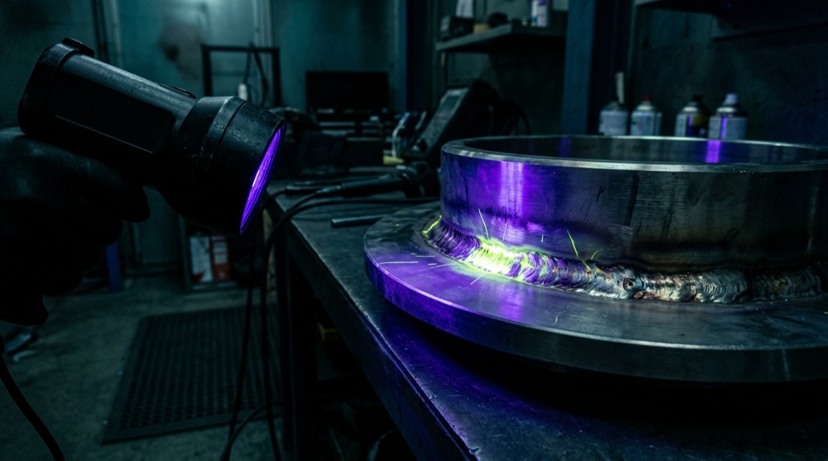
Lighting is the other big difference. With color contrast penetrants ISO 3059 requires at least 500 lux at the test surface, a value a handheld lamp doesn't always deliver under a tank or inside an enclosed structure. With fluorescent penetrants you need a UV-A source centered on 365 nm delivering at least 10 W/m² (1000 µW/cm²) at the surface and a nearly dark area, with no more than 20 lux of visible light, plus time for the inspector's eyes to adapt. Yellow-green indications on a dark background stand out far better than a red mark on white, which is why aerospace and series production work with fluorescent penetrants inside darkened booths.
| Aspect | Color contrast (Type II) | Fluorescent (Type I) |
|---|---|---|
| Viewing | White light, at least 500 lx | UV-A 365 nm, at least 10 W/m², ambient light up to 20 lx |
| ISO 3452-2 sensitivity levels | 1 (normal), 2 (high) | ½, 1, 2, 3, 4 |
| Typical use | Field work, maintenance, large parts, occasional testing | Workshop, booth, series production, critical components |
| Minimum equipment | Aerosol cans, cloths, light meter | UV-A lamp, radiometer, area that can be darkened |
| Weak point | Limited contrast on fine indications | Needs real darkness, hard to achieve outdoors |
On welds the choice follows the surface as well as the sensitivity. Annex A of ISO 23277 recommends, for acceptance level 1, a fine surface and a fluorescent system of normal sensitivity or higher, or a high-sensitivity color contrast system. At levels 2 and 3, with smooth or as-welded surfaces, it accepts any system. On a rough MAG weld cap with spatter and ripples, a highly sensitive fluorescent product mostly produces background and nonrelevant indications, and local grinding helps more than a stronger product.
Liquid penetrant kits: what they should contain
A kit is judged by its product family more than by its cans. Under ISO 3452-1 a family is the set of penetrant, remover and developer approved together to ISO 3452-2 and coming from the same manufacturer. Pairing one family's penetrant with another family's developer means working with a system nobody has qualified, and in a third-party audit it becomes a nonconformity. Before buying, it pays to check the following:
- penetrant, remover and developer from the same family, with an ISO 3452-2 designation (type, method, developer form and sensitivity level) and a batch certificate;
- products designated low in sulfur and halogens when testing austenitic stainless steel, nickel alloys or titanium, materials for which ASME Section V sets content limits;
- a Type 2 reference block to ISO 3452-3, to check periodically that the process still gives the same indications;
- clean lint-free cloths, dedicated brushes and a contact thermometer for the surface;
- a light meter for color contrast systems, while fluorescent systems need a 365 nm UV-A lamp, a radiometer and an area that can be darkened;
- for work below 10 °C or above 50 °C, products qualified for that temperature to ISO 3452-6 or ISO 3452-5.
Aerosol cans have an expiration date and don't like the cold. A check on the reference block at the start of the shift, compared with a photo of the indications obtained with a new system, tells you in a few minutes whether the products still work as they did on qualification day. For conventional UV-A lamps, the ASTM aerospace practice also calls for a ten-minute warm-up before use, a requirement that does not apply to LED sources.
Need to choose penetrant testing kits and materials?
Tell us the material, joint type, surface finish, temperature and required acceptance level: we help you choose liquid penetrant kits, products and equipment, and we tell you whether another method suits that flaw better. Reply within 24 hours.
Email us Message us on WhatsAppWeld acceptance levels under ISO 23277
The ISO 3452 series describes how the test is performed, but it doesn't say when an indication is acceptable. For metallic welds that job belongs to ISO 23277, which separates linear indications, with a length greater than three times the width, from nonlinear ones and sets three acceptance levels.
| Acceptance level | Linear indication (length l) | Nonlinear indication (major axis d) |
|---|---|---|
| 1 | l ≤ 2 mm | d ≤ 4 mm |
| 2 | l ≤ 4 mm | d ≤ 6 mm |
| 3 | l ≤ 8 mm | d ≤ 8 mm |
The test area covers the weld metal and the parent metal up to 10 mm on each side. Indications roughly in line and separated by less than the length of the shorter one count as a single continuous indication, while grouped indications are outside the scope of the standard. Levels 2 and 3 can carry the suffix X, which means every linear indication must be evaluated to level 1. The standard itself warns that in this case the probability of detecting the smaller indications can be low. Asking for 2X on an as-welded cap tested with a color contrast kit means expecting more from the test than the surface and products can reliably show.
The level to apply is not the inspector's choice. The link with the quality levels of ISO 5817 for steel, nickel and titanium and ISO 10042 for aluminum is set out in ISO 17635, last revised in 2025, while the level itself comes from the product standard, the code or the contract. The same logic applies to radiography, as explained in the article on weld radiography acceptance levels. When an indication is rejected and the specification allows it, the imperfection can be reduced or removed by local grinding, and the area is then retested with the same system and technique.
Who performs the test and which standards to cite
ISO 3452-1 recommends personnel certified to ISO 9712, which defines three levels for the PT method. Level 1 carries out the test following written instructions, Level 2 sets up the technique and interprets and evaluates results against the applicable standard, and Level 3 develops and approves procedures and techniques. The same standard also requires the operating authorization to be issued by the employer under a written procedure.
| Standard | What it covers |
|---|---|
| EN ISO 3452-1:2021 | General principles, steps, times, process control |
| EN ISO 3452-2:2021 | Testing and classification of penetrant materials, sensitivity levels |
| EN ISO 3452-3 | Type 1 and Type 2 reference blocks |
| EN ISO 3452-4 | Equipment |
| EN ISO 3452-5 and 3452-6 | Testing above 50 °C and below 10 °C |
| EN ISO 3059 | Viewing conditions for penetrant and magnetic particle testing |
| EN ISO 23277:2015 | Acceptance levels for welds |
| ISO 17635:2025 | General rules for NDT of welds and link with ISO 5817 |
| EN ISO 9712 | Qualification and certification of personnel |
| ASTM E165/E165M, ASTM E1417/E1417M, ASME BPVC Section V | References for US projects, aerospace and pressure equipment |
Where the method stops: magnetic particle, ultrasonic or radiographic testing
On the page about non-destructive testing the typical scheme for a weld is clear: visual testing on every joint, a surface method and a volumetric method on the required percentage. Liquid penetrant testing covers only the surface step, and even there it is not always the best choice.
| What you are looking for | Best-suited method | Why |
|---|---|---|
| Surface cracks on ferritic steels | Magnetic particle testing (MT) | Faster, and also sensitive to discontinuities just below the surface (ISO 17638, ISO 23278) |
| Surface cracks on austenitic stainless steel, aluminum, nickel, titanium | Penetrant testing (PT) | Simple surface method on nonmagnetic materials |
| Lack of fusion and internal cracks in medium and heavy sections | Ultrasonic testing (UT, PAUT, TOFD) | Volumetric method, gives flaw position and height |
| Porosity, inclusions, incomplete penetration, archived records | Radiographic testing (RT) | Permanent image, ISO 10675-1 levels |
| Internal surfaces of pipes and cavities out of reach | Remote visual inspection (RVI) | Takes the inspection where penetrant can't be applied |
When the question is which volumetric method to use, the comparison of radiography and ultrasonic testing for welds helps you decide based on thickness, joint type and expected flaw. For equipment, the pages on ultrasonic testing, industrial radiography and industrial borescopes and endoscopes describe how we help you choose. The right answer often combines two methods, for example penetrant testing on the back-gouged root of a stainless steel joint and radiography on the completed weld.
What to send us for an assessment
To help you choose liquid penetrant kits, products and equipment, or to find out whether your case calls for another method, we need a few details:
- base and filler material (carbon steel, stainless steel, aluminum, nickel alloys, titanium);
- joint or part type (butt weld, fillet weld, casting, machined component) and surface finish;
- part dimensions and length of the welds to be tested;
- volumes, meaning parts or meters of weld per day or per month;
- reference standard or specification and the required acceptance level;
- working environment (workshop, booth, outdoor site) and surface temperature.
You can send them by email to info@dipitech.com or on WhatsApp, attaching a photo of the joint and your current procedure if possible, or fill in the contact form. We reply within 24 hours, with technical support in Italy.
With this information the right system can be defined, color contrast or fluorescent, aerosol or line-based, together with reference blocks and light measurement instruments. If penetrant testing isn't enough, the assessment moves on to magnetic particle testing of welds, ultrasonic or radiographic testing.
Request a quote
Leave your name, email, and a few lines about your application, with no obligation. We reply within 24 hours with initial technical guidance and a quote.
Frequently asked questions about liquid penetrant testing
What is liquid penetrant testing used for?
It is a non-destructive testing method that reveals discontinuities open to the surface, such as cracks, porosity and surface-breaking lack of fusion. A dyed or fluorescent liquid enters the flaws by capillary action, the excess is removed and a white developer draws out the trapped liquid, forming a visible indication. Typical applications are welds, castings, forgings and in-service components, on almost any nonporous material, including austenitic stainless steel, aluminum and titanium.
How is penetrant testing performed on welds?
ISO 3452-1 sets six steps: cleaning and drying the weld and the adjacent parent metal, applying the penetrant, removing the excess with a dry cloth and then a solvent-moistened cloth, applying a thin developer layer, inspecting under proper lighting and recording, and postcleaning. Products and surface must stay between 10 and 50 °C, and times and products must be written into the procedure.
How long should the penetrant dwell time be?
Under ISO 3452-1 the penetrant dwell time runs from 5 to 60 minutes and must not be shorter than the manufacturer's recommendation for the required sensitivity. Developer time is normally between 10 and 30 minutes, with a first look right after application. On rough surfaces and some alloys indications form more slowly, so times should be set in the procedure and checked on the reference block.
What is the difference between fluorescent and color contrast penetrants?
Color contrast penetrants, usually red on white developer, are viewed under white light of at least 500 lux and are practical in the field. Fluorescent penetrants are viewed under 365 nm UV-A light, with at least 10 W/m² at the surface and no more than 20 lux of ambient light, and reach higher sensitivities: ISO 3452-2 defines five levels for them versus two for color contrast systems. In return they need a darkened area, usually a booth.
What should a liquid penetrant testing kit contain?
Penetrant, remover and developer from the same product family, qualified to ISO 3452-2, with a batch certificate and, for austenitic stainless steel, nickel alloys and titanium, low sulfur and halogen content. The kit is completed by lint-free cloths, an ISO 3452-3 reference block for process checks, a surface thermometer and, for fluorescent systems, a UV-A lamp and a radiometer. DIPITECH helps you choose the kit that suits your material, standard and working environment.
Which standards apply to liquid penetrant testing?
The method is governed by the ISO 3452 series: Part 1 for general principles, Part 2 for materials, Part 3 for reference blocks, Parts 5 and 6 for temperatures outside the 10-50 °C range. Viewing conditions are in ISO 3059. For welds, acceptance levels are in ISO 23277, linked to ISO 5817 through ISO 17635, and personnel are certified to ISO 9712. In the US, ASTM E165, ASTM E1417 and ASME Section V are used.
When should you use penetrant testing instead of magnetic particle or ultrasonic testing?
Penetrant testing is for surface-breaking flaws on any nonporous material and is the natural choice on austenitic stainless steel, aluminum and titanium. On ferritic steels magnetic particle testing is faster and also detects discontinuities just below the surface. Internal flaws such as lack of fusion or inclusions call for volumetric methods, ultrasonic or radiographic testing, chosen according to thickness and joint type.