
Among non-destructive tests on carbon and low-alloy steel welds, magnetic particle testing, also called magnetic particle inspection or MPI, is the most widely used surface method in structural fabrication, boiler and pressure vessel shops, forges and maintenance departments. It is done in the shop or in the field with a portable yoke, needs only modest surface preparation and reveals fine, tight cracks that visual inspection misses, including those running just below the surface.
The risk lies in mistakes that leave no trace. A field that is too weak, a single magnetization direction, a UV lamp that has lost output or a bath that is too dilute all give a result with no indications, identical to that of a sound joint. So before talking about equipment, it helps to understand what makes the test reliable and what makes it fail without anyone noticing.
How it works: magnetic flux leaking out of the crack
The principle is physical and fairly intuitive. The part, or the area to be tested, is magnetized and the flux lines run inside the ferromagnetic material. Where they meet a discontinuity that cuts across them, such as a crack, part of the flux is forced out into the air and back in beyond the flaw. This leakage field attracts the ferromagnetic particles spread on the surface, which build up over the crack and trace its outline, often wider and more visible than the crack itself.
That leads to the first practical rule. The signal is strongest when the field is perpendicular to the discontinuity and fades to nothing as the two become parallel. Placing the yoke poles on either side of the bead makes the flux cross the weld and reveals longitudinal cracks, while poles aligned along the bead bring out the transverse ones. This is why ISO 17638 requires each area to be magnetized in two roughly perpendicular directions, with a maximum deviation of 30°, and advises against testing in one direction only unless a product standard calls for it.
The second rule concerns depth. The method finds surface-breaking discontinuities and those just below the surface, but sensitivity drops quickly with depth, as ISO 9934-1 points out. The waveform matters too. With alternating current the flux is concentrated in a thin surface layer by the skin effect, and the oscillating field keeps the particles moving. This is the best condition for surface-breaking cracks, which is why ISO 17638 makes AC equipment the default choice for welds. Direct current penetrates deeper and helps with subsurface discontinuities, but leaves residual magnetism that is harder to remove. Under the same standard, DC yokes and permanent magnets may only be used if agreed at the time of order.
When it applies: ferromagnetic materials only
The sharpest limit is the material. The method works on anything that can be magnetized, so carbon and low-alloy steels, ferritic and martensitic stainless steels, cast irons and many quench-and-temper and tool steels. It does not work on austenitic 300-series stainless steels, aluminum, copper, titanium or nickel-based superalloys. In those cases surface inspection moves to liquid penetrant, which has the opposite advantage of not depending on the material but only finds what is open to the surface. The ASTM E3024/E3024M practice for general industry explicitly excludes austenitic steels from its scope.
Then there are dissimilar joints, for example carbon steel welded with austenitic filler metal. The jump in magnetic permeability along the fusion line attracts particles even where there is no flaw and produces non-relevant indications that an inexperienced operator can mistake for cracks. On these joints it often makes sense to switch to penetrant, or at least to interpret with great care.
In production plants the typical uses repeat themselves. In structural steel fabrication, fillet and butt welds are tested, and EN 1090-2 sets a hold time before inspection so that any hydrogen cracks have time to appear. In pressure equipment work the targets are joints on ferritic steel vessels and piping, back-gouged roots and prepared edges before welding. In forges and foundries, bench magnetic particle testing is the standard production check for shafts, flanges, hooks, connecting rods and steel castings. In maintenance it is used to look for fatigue cracks on cranes, overhead cranes, frames and lifting gear without dismantling them.
Yoke, bench unit, coil, prods: which equipment for which part
Choosing magnetic particle testing equipment follows part geometry, test location and volumes. The table summarizes the four families met most often.
| Equipment | How it magnetizes | Typical use | What to check |
|---|---|---|---|
| Electromagnetic yoke | Flux between two pole pieces placed on the part | Welds in the shop and in the field, repairs, maintenance | Lifting force or tangential field, pole spacing, overlap of the examined areas |
| Prods | Current passed through the part between two electrodes | Heavy plate, castings and large structures | Arc burns at the contact points, to be removed and retested |
| Coil or wrapped cable | Longitudinal field from a conductor wound around the part | Pipes, shafts, nodes and elongated parts | Length-to-diameter ratio, coil fill factor, number of turns and current |
| Bench unit | Current between headstock and tailstock (circular field) and coil (longitudinal field) | Forgings, shafts, fasteners and production parts | Current set per part number, bath, darkened booth, inline demagnetizer |
The yoke is by far the most common equipment on welds. The US documents, namely the ASTM E709 guide and ASME Section V, check its performance with a lift test. An AC yoke must lift at least 10 lb (4.5 kg) at the maximum pole spacing to be used in inspection, while the requirements for DC and permanent magnets are higher. The European approach of ISO 17638 looks instead at the field tangential to the surface. For structural steels it recommends 2 to 6 kA/m rms, verified with a Hall effect probe, a reference part containing known flaws or other recognized methods. Shim-type indicators give an idea of field direction and order of magnitude, but the standard states that they are not enough to prove the field is adequate.
On the job, two geometric details make the difference. Near each pole the field is so intense that particles build up everywhere and the area cannot be evaluated, so the useful areas have to overlap as the yoke moves along the bead. In the ISO 17638 diagrams the pole spacing is at least 75 mm, and the effectively magnetized area has to cover the whole weld and heat-affected zone.
Prods pass current directly through the part and magnetize wide areas even on heavy sections. The price is the risk of arcing and burns at the contact points, which on sensitive steels can themselves become crack initiation sites. ISO 17638 requires this risk to be minimized, the burns to be removed and the area to be retested with a suitable method.
The bench unit is the shop machine for production work. The part is clamped between headstock and tailstock and magnetized in two ways. Current flowing through it creates a circular field that reveals longitudinal flaws, and the coil creates a longitudinal field for transverse ones. With a fluorescent bath, a darkened booth and an inline demagnetizer, one operator can inspect shafts, connecting rods and flanges at production pace. When parts are all the same, repeatability matters most, built on currents fixed per part number, daily checks and a reference part with known flaws.
Need to choose a yoke, a bench unit or the right method?
Tell us the material, joint or part type, dimensions and volumes. We help you choose yokes, bench units, consumables and UV lamps, or a different method if your case calls for it. Reply within 24 hours.
Email us Message us on WhatsAppDry or wet, visible or fluorescent
Particles are applied in two ways. In the dry method, a ferromagnetic powder is blown onto the area while the part is magnetized. It works on rough, as-cast or as-welded surfaces, can be used on hot surfaces within the temperature limits stated by the powder manufacturer and is practical on site, but with coarser particles its sensitivity to the finest cracks is lower. The wet method uses much smaller particles, suspended in a water- or oil-based carrier, which migrate easily toward the leakage field. It is the reference method for fine cracks.
The second choice is how indications are viewed. In color contrast testing, the most common on structural welds, a thin white paint goes on first and the black magnetic ink is applied over it. Work is done under white light, and ISO 3059 requires at least 500 lx at the surface. In fluorescent magnetic particle testing the particles carry a pigment that, excited by UV-A radiation, emits yellow-green light, the color the eye is most sensitive to in low light. Contrast rises sharply and so does sensitivity to fine flaws, provided the viewing conditions are controlled.
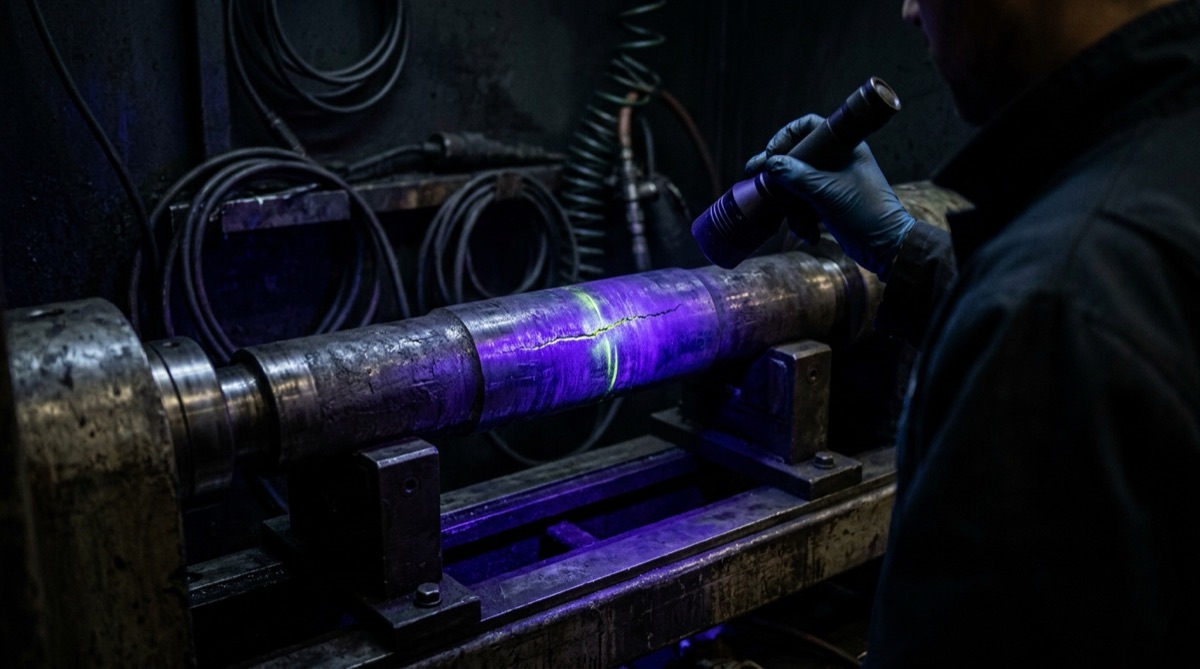
For fluorescent testing, ISO 3059 sets a UV-A irradiance of at least 10 W/m² (1000 µW/cm²) at the examined surface, with ambient light no higher than 20 lx, as a paper presented at the ECNDT 2023 European conference also summarizes. The radiation is centered on 365 nm, and LED lamps have almost completely replaced mercury vapor lamps. Specifications for LED lamps also limit the visible light they emit, which causes glare and reduces contrast. Before starting, the operator allows the eyes to adapt to the dark, and procedures prohibit photochromic glasses. A calibrated UV radiometer and light meter are as much part of the equipment as the lamp, and intensity checks have to be recorded.
Finally, the wet bath has to be kept under control. Concentration is checked with a graduated settling tube, within the limits given by the procedure and the ink manufacturer, while contamination shows up when the bath is compared with a fresh sample. A dilute or dirty bath returns a uniform background and no indications, a false negative that goes unnoticed.
Standards for magnetic particle testing of welds
In Europe the standards are split by topic. ISO 9934-1 sets the general principles of the method, ISO 9934-2 the properties of detection media (inks, powders, carrier liquids, contrast paints) and ISO 9934-3 the equipment. For welds the technique standard is ISO 17638, which covers equipment, recommended field, directions and overlaps, and refers to ISO 3059 for viewing conditions.
ISO 17638 does not, however, say what is acceptable. The criteria are in ISO 23278, which defines three acceptance levels for indications on ferromagnetic steel welds and treats linear and nonlinear indications differently. The link to the weld quality levels of ISO 5817 is provided by ISO 17635, the general standard on non-destructive testing of welds, revised in 2025. The logic is the same as in radiography, described in the article on who decides weld acceptance levels.
Magnetic particle testing is always preceded by visual testing to ISO 17637, and whoever performs and evaluates the test must be qualified. ISO 17638 recommends certification to ISO 9712, where the method is designated MT. On projects built to US codes the references become the ASTM E709 guide, the ASTM E3024/E3024M practice for general industry, ASTM E1444/E1444M for aerospace and Article 7 of ASME Section V.
Demagnetization: when it is needed and how it is checked
After testing, the part can remain magnetized, especially with direct current and on high-coercivity steels. Residual magnetism causes problems in specific situations. It deflects the arc in later welding, known as arc blow, holds chips and dust during machining, speeds up wear of bearings and sliding surfaces and interferes with instruments and sensors mounted near the part. That is why ISO 17638 lists demagnetization among the items to be agreed before testing.
The most common technique exposes the part to an alternating field that decreases gradually to zero, either by passing it through a coil or by ramping down the current. Parts magnetized with DC are treated with reversing DC cycles of decreasing amplitude, which reach deeper. The result is measured with a field meter, and the allowed limit is set by the customer specification or the applicable procedure, usually stricter for parts to be welded or precision machined. Anyone choosing a bench unit or a yoke would do well to ask early on how demagnetization will be handled, because reworking a part costs more than the test.
Limits of the method and comparison with penetrant, ultrasonic and radiographic testing
The limits of magnetic particle testing follow from its principle. The test covers the surface and the layer just beneath it, so internal porosity, inclusions and lack of fusion in the middle of the joint stay out of reach. It sees flaws parallel to the field poorly, hence the need for two directions. Thick coatings, scale and weld spatter reduce the useful field and create background, so the surface has to be prepared, including local grinding when bead ripples confuse interpretation. Sharp corners, section changes and areas near the poles produce non-relevant indications that the operator must be able to recognize.
Compared with liquid penetrant, on ferritic steels magnetic particle testing is faster and copes better with a crack filled with oxide or dirt, which would block the penetrant. Penetrant remains the only surface option on nonmagnetic materials and dissimilar joints, though. The detailed comparison is in the article on liquid penetrant testing of welds.
The weld volume needs other methods. Industrial ultrasonic testing with PAUT and TOFD finds and sizes lack of fusion and planar cracks through the thickness, and the phased array technique is explained in the PAUT guide. Industrial radiography records porosity, inclusions and volumetric flaws in an image that can be archived, with strengths and limits discussed in the comparison of industrial radiography and ultrasonic testing. How these methods combine in an inspection plan is explained in the guide to non-destructive testing.
What to send us for an assessment
To suggest the right equipment and method for your case we need a few details:
- base and filler material, flagging any dissimilar joints;
- joint or part type (butt, fillet, nodes, forgings, castings);
- dimensions and geometry, with minimum thicknesses and diameters;
- volumes and inspection frequency, from one-off parts to series production;
- standard and acceptance level required by the specification or the customer;
- test location, in the field or in the shop, with available power supply and lighting conditions.
You can send them by email to info@dipitech.com, on WhatsApp or through the contact form, attaching a few photos of the part and the procedure in use if you have them.
With this information we help you choose yokes and magnets, bench units, detection media and UV lamps. We also tell you whether, for the flaw you expect, magnetic particle testing is really the right method or whether penetrant, ultrasonic or radiographic testing should be added. You get a reply within 24 hours.
Frequently asked questions about magnetic particle testing
What is magnetic particle testing and how does it work?
It is a non-destructive test for ferromagnetic materials. The area to be examined is magnetized and very fine ferromagnetic particles, either visible or fluorescent, are applied. Where a crack interrupts the flux, part of the field leaks into the air and attracts the particles, which build up over the flaw and outline it. The method finds surface-breaking and slightly subsurface discontinuities, especially when they lie across the field.
Can magnetic particle testing be used on stainless steel?
Only on magnetic stainless grades, meaning ferritic and martensitic. Austenitic 300-series stainless steels such as 304 and 316 cannot be magnetized and call for liquid penetrant testing. The same applies to aluminum, copper, titanium and nickel-based superalloys. On joints between carbon steel and austenitic stainless steel, the change in permeability along the fusion line produces non-relevant indications, and penetrant is usually the safer choice there too.
Is magnetic particle or penetrant testing better for welds?
On ferritic steels magnetic particle testing is generally faster, copes better with tight cracks or cracks filled with oxide, and also finds discontinuities just below the surface. Liquid penetrant works on any nonporous material, but only on flaws open to the surface and only after thorough cleaning. The choice therefore depends first on the material, then on the product standard or the specification.
What is the difference between visible and fluorescent magnetic particle testing?
With the color contrast method, black particles are viewed on a white contrast paint under white light of at least 500 lx according to ISO 3059. With the fluorescent method, the particles glow yellow-green under UV-A radiation, with at least 10 W/m² at the surface and ambient light no higher than 20 lx. Fluorescent testing is more sensitive to fine flaws but needs a darkened area and verified lamps and meters, so it is used mostly in the shop and on bench units.
Which standards govern magnetic particle testing of welds?
The technique is defined by ISO 17638, acceptance levels by ISO 23278, general principles by ISO 9934-1, with parts 2 and 3 covering detection media and equipment, and viewing conditions by ISO 3059. Personnel qualification follows ISO 9712. On projects built to US codes, the references are the ASTM E709 guide, the ASTM E3024/E3024M or E1444/E1444M practices and Article 7 of ASME Section V.
What equipment is needed for magnetic particle testing?
For field weld inspection an AC electromagnetic yoke is usually enough, together with contrast paint, magnetic ink, a field indicator and a light meter. The fluorescent method adds a UV-A lamp and a radiometer. In the shop, on production parts such as shafts and forgings, a bench unit with a fluorescent bath, a darkened booth and a demagnetizer is used. Prods and coils serve heavy sections and elongated parts.
Does a part need to be demagnetized after magnetic particle testing?
It depends on what happens to the part next. Residual magnetism can deflect the arc in later welding, hold chips during machining or interfere with instruments and bearings. Demagnetization uses a decreasing AC field or reversing DC cycles, and the residual field is measured with a field meter. The allowed limit is set by the customer specification or the applicable procedure.