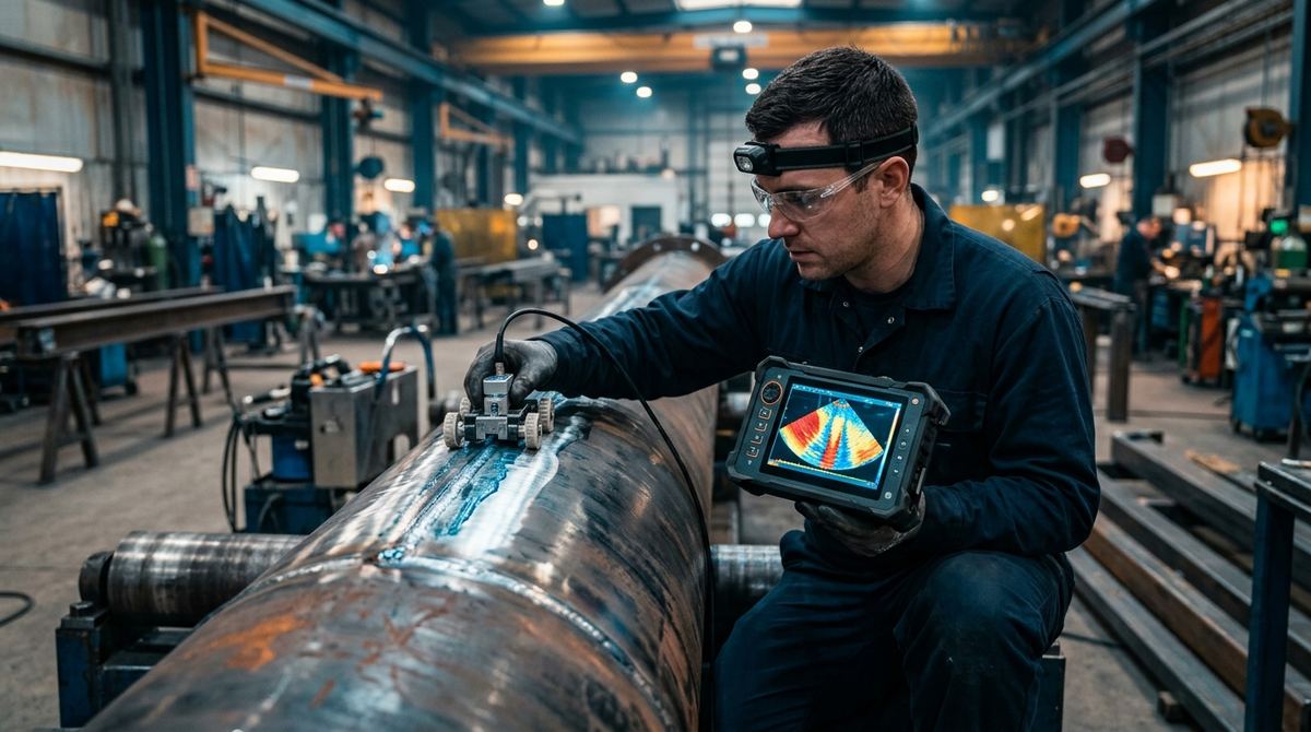
In conventional ultrasonic testing the operator watches a signal, the A-scan, interprets it while moving the probe and, at the end of the shift, all that's left of what was seen is the report. Phased array ultrasonic testing (PAUT) changes both things. It produces cross-sectional images of the material and records the data together with the probe position, so the inspection can be reopened, reanalyzed and compared years later. It has therefore become the reference technique for ultrasonic NDT of critical welds, corrosion mapping and components with complex geometry. Moving over from conventional UT has a cost that goes beyond the instrument, though, and it pays to know in advance where it is recovered.
Many elements, one beam steered by electronics
A phased array probe contains many small piezoelectric elements, usually 16, 32, 64 or 128, arranged in a linear or matrix array, and each one can be fired with its own delay. With the right delays, the wavefronts from the individual elements add up to a single beam whose two properties are controlled electronically. The first is the angle. Delays that increase along the array tilt the resulting wavefront, which is beam steering. The second is the focus, because parabolic delay profiles concentrate energy at a chosen depth, improving resolution and signal-to-noise ratio in that zone. The set of delays that produces a given angle at a given depth is called a focal law.
On reception the process runs in reverse, with the signals from each element delayed and summed in phase. This gives the three typical PAUT views. The S-scan, or sectorial scan, sweeps a range of angles electronically, for example 40° to 70°, and builds the fan-shaped image of the cross section that has become the symbol of phased array. The E-scan, or linear scan, steps the same group of focal laws along the array and moves the beam at a constant angle, like a conventional probe sliding along without being moved. The C-scan appears when the probe is mounted on an encoded scanner and the data are plotted in plan view over the surface. It is the view used in ultrasonic corrosion mapping.
The physics is still that of classic ultrasonics, with reflection at interfaces, mode conversion and attenuation. What changes is control of the beam and the amount of information collected on each pass.
Phased array and conventional UT compared
| Aspect | Conventional UT | Phased array (PAUT) |
|---|---|---|
| Angular coverage | One angle per probe or wedge (45°, 60°, 70°) | A range of angles in a single pass (S-scan) |
| Data display | A-scan, interpreted in real time | S-scan, E-scan and C-scan images plus A-scan |
| Recording | Usually none, only the report | Full data with encoder position, available for reanalysis |
| Repeatability and audit | Depends on the operator | Encoded scan, comparable over time |
| Speed on welds | Several passes with several probes | One or two passes along the joint |
| Instrument and set-up cost | Low | Higher; requires a scan plan and more elaborate calibration |
| Personnel | UT Level 2 to ISO 9712 | UT to ISO 9712 plus phased array specific training |
The most underestimated row is the last one, together with the scan plan it presupposes. Without a proper plan, meaning weld volume coverage, angles, focal laws and calibration on blocks with known reflectors, the color image only gives an illusion of completeness. Personnel training is part of the real cost of adoption as much as the instrument.
Want to know whether phased array pays off on your joints?
Describe the joints or components, thicknesses, materials and annual volumes, and we'll tell you whether moving from conventional UT pays off and with which configuration.
Email us Message us on WhatsAppWhere PAUT delivers the most
Welds remain the core application: butt welds on piping and pressure vessels, structural joints, fillet welds with limited access. The swept beam catches planar flaws in different orientations, such as lack of sidewall fusion, lack of penetration and cracks, and the image helps locate them and size their height. On thick welds phased array often works alongside TOFD, which measures flaw height from the signals diffracted at the flaw tips, with both probe sets mounted on the same scanner.
In corrosion work the gain is data density. A C-scan map of remaining wall on piping, shells and tank floors collects thousands of positioned readings in one pass, and two encoded maps taken years apart give an estimate of the corrosion rate zone by zone. For spot readings at the CMLs the ultrasonic thickness gauge is still the tool. On aerospace composites, linear arrays at 0° with a high element count look for delaminations, porosity and inclusions. On complex geometries such as bushings, shafts and blade roots, phased array adapts the beam in software where conventional UT would need a dedicated wedge for every angle, and matrix probes can even steer it out of plane.
Advantages and limits, weighed together
The advantage that carries the most weight in contracts is recording. Complete data can be reanalyzed afterwards, given a second opinion, shown to the end client in an audit and archived for the next comparison. On top of that come fewer passes for the same coverage, images that reduce interpretive ambiguity and a better probability of detecting planar flaws in any orientation. Then there is replacing radiography on many welds, which the main construction codes allow under specific conditions, with the benefit of working without radiation sources and without areas to clear on site. When radiography is still the better choice is covered in the comparison of industrial radiography and ultrasonic testing.
The limits are just as concrete. The initial investment is higher, because it includes instrument, probes, scanner, software and training, and results depend on the quality of the scan plan and the calibrations. Coupling has to be ensured on irregular surfaces too. Coarse-grained and anisotropic materials, such as austenitic welds and nickel alloys, deflect and attenuate the beam and need dedicated transmit-receive longitudinal wave probes. And the image doesn't replace skill, because classifying an indication remains the judgment of a qualified Level 2 or Level 3 operator.
The chain of standards that decides whether a joint passes
A specification that says only "phased array testing to ISO 13588" leaves the contract open. ISO 13588:2019 sets out how semi-automated and automated testing of steel joints from 6 mm upward is performed, with four testing levels and requirements for procedure and equipment, but it contains no acceptance criteria. Those are in ISO 19285:2017, which sets three acceptance levels for indications detected to ISO 13588, tied to the quality levels of ISO 5817. Level 1 is the strictest, and that counterintuitive direction is worth clarifying with the client before acceptance testing.
On thin walls the pair changes. ISO 20601:2018 covers phased array testing of thin-walled steel components between 3.2 and 8 mm thick. Unlike ISO 13588, though, it comes without a companion acceptance standard, so acceptance levels have to come from the product code or be agreed in the contract. Personnel are certified for the UT method to ISO 9712:2021, with phased array specific training that specifications and technique standards often ask to be documented. Instruments, probes and complete systems are verified to the three parts of the ISO 18563 series, from Part 1 (2022) to Part 3 (2024). On austenitic and duplex steels, nickel alloys and dissimilar joints, ISO 22825:2017 applies in addition and requires the procedure to be qualified on the actual material.
Under US codes the picture is different. ASME Section V, Article 4, governs ultrasonic examination for vessel and piping codes, including the requirements for techniques with recorded data, and acceptance criteria come from the construction code. ASTM E2700-26 describes contact phased array testing of welds. Anyone starting from procedures written to ISO 17640:2018, the standard for conventional UT of welds, therefore has to rewrite procedure and acceptance criterion together. If either one is missing, the report won't hold up at acceptance.
Choosing the instrument is a separate job
Channel architecture, groups acquired in the same pass, the kit of probes, wedges and scanners, software and verification to ISO 18563 decide whether an instrument can meet the specification. They weigh on inspection cost more than the list price does. We have collected them, with the questions to ask the supplier, in the article on how to choose a PAUT and TOFD instrument before you buy. Here it is enough to state the underlying rule, which is that the configuration follows from the inspection to be performed and the standard that will judge it. FMC/TFM, now governed by ISO 23865:2021, enters the picture when the expected flaws call for it.
When moving from UT to PAUT pays off
The move pays off when inspections are recurrent and volumes justify the higher productivity, or when the client and the code ask for recorded, traceable data. It also pays off when geometries would multiply the number of conventional probes, when radiography has to be replaced for safety or to keep the site running, and when corrosion maps must remain comparable over time. With occasional inspections, simple geometries and nobody asking for recorded data, the cost of instrument, training and qualification is not recovered.
A sound evaluation therefore starts from the application: joints or components to inspect, thicknesses and materials, expected flaws, acceptance criteria, annual volumes. On that basis configuration and procedure are defined and then tested on the real part; the available solutions are collected on the page for industrial ultrasonic testing instruments for PAUT and TOFD.
What to send us for an assessment
To tell you whether phased array pays off on your inspections we need a few precise data points:
- joints or components to inspect, with a drawing or photo;
- material, thicknesses and, for pipe, outside diameter;
- expected flaws and the standard or acceptance criterion required by the client;
- annual or monthly volumes and field access conditions;
- current method (conventional UT, radiography, outside service) and available instruments;
- ISO 9712 certification level of your personnel.
You can send them by email to info@dipitech.com or on WhatsApp, attaching drawings or photos. With this data DIPITECH prepares a tailored quote within 24 hours and, if needed, a test on your component, with no obligation.
Frequently asked questions about phased array ultrasonic testing (PAUT)
What is phased array ultrasonic testing (PAUT)?
An ultrasonic technique in which the probe is divided into many elements fired with different delays, so that the beam is steered and focused electronically. The name comes from controlling the phase of the individual pulses, the same principle used in phased array radar antennas. In NDT it spread once portable instruments became able to compute the focal laws of an entire scan in the field and record the data.
What is the difference between PAUT and conventional ultrasonic testing?
On the same weld, conventional UT covers the angles by changing probe or wedge and leaves a report at the end; PAUT covers the same range in one pass and leaves a file. The difference shows most in an audit, because a disputed indication can be reviewed on the recorded data instead of repeating the inspection in the field.
Which standards govern PAUT of welds?
Under ISO the pair is technique plus acceptance: ISO 13588:2019 and ISO 19285:2017 from 6 mm upward, ISO 20601 between 3.2 and 8 mm. Under ASME, Section V, Article 4 applies, with the acceptance criteria of the construction code. Specifications most often go wrong by citing only the technique standard and leaving the acceptance level undefined.
Can PAUT replace radiography on welds?
In many cases it can, and that is one of the most common reasons for adopting it, because it removes the controlled area to clear and the source to transport. Radiography remains easier to read on some volumetric flaws, such as scattered porosity and inclusions, and on certain geometries; the choice depends on expected flaws, thickness, access and the requirements of the applicable code.
What is TFM and is it really needed?
The Total Focusing Method reconstructs the image by focusing at every point of the region of interest, starting from a Full Matrix Capture acquisition in which each element transmits in turn and all elements receive. It gives sharper images of small flaws and flaws near surfaces, at the price of heavier files and slower scans. Since 2021 it has been standardized by ISO 23864 for welds and ISO 23865 for general use.