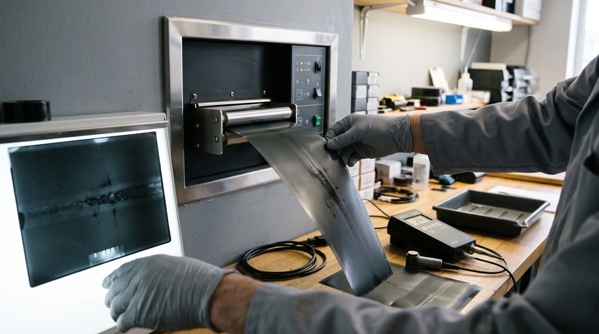
A radiograph of a pipe weld comes back from the client with a note in the margin: density 1.8 in the weld area, shot to be repeated. The exposure followed the qualified technique, the source was the same as the day before and the image quality indicator barely reached the required value. What had changed was the processing. For a week the developer had been running a few degrees below its working temperature, and a replenishment pump had been dosing less than it should. Nobody noticed, because a slow drift does not show when you look at radiographic film on the viewer. It shows only when a film drops below the threshold and is sent back.
Anyone still working on film, and in Italy many NDT labs, fabricators, foundries and oil & gas field crews do, knows this situation well. Chemical processing is the least controlled link in the radiographic chain, for a simple reason: the technician decides the exposure with calculations and charts, while processing is taken for granted as long as the machine is switched on. The page on industrial X-ray film processors explains how to choose the equipment. The problem has another end, though: the defects that processing leaves on the film, and how to catch them before the client does.
Why a well-exposed film can come out of specification
ISO 17636-1:2022, the standard for film radiography of welds, requires an optical density in the area of interest of at least 2.0 for technique class A and at least 2.3 for class B. The upper limit depends on the viewer, which must provide enough luminance to read the higher densities according to ISO 5580:2023. In this range the film gradient, which rises with density, is high enough for the wires or holes of the image quality indicator to stand out from the background as expected.
Density, however, does not depend on exposure alone. ISO 11699-1:2008 classifies film systems, from class C1 to C6, by measuring gradient and granularity on film processed under defined conditions. The class therefore belongs to the pairing of film and process, and the same emulsion developed in a tired bath loses contrast and speed. A procedure that states "film system class C4" is implicitly stating the chemicals, temperature and time specified by the film manufacturer as well. If processing drifts outside those conditions the class is no longer guaranteed, even though nobody changed a line of the document.
For a sense of scale, the classic reference for manual tank development is about 5 minutes at 20 °C. Automatic processors run warmer, often around 28 °C, with a dry-to-dry cycle of about 8 minutes in the standard version and shorter in rapid ones. Replenishment is dosed in milliliters of fresh solution per area of film processed. The exact time, temperature and dosing figures are in the film and chemistry data sheets, and that is what the procedure should refer to.
The practical consequences come in two forms. Weak development lowers density, and the technician compensates with longer exposures, meaning more time in the controlled area and more dose to manage under the radiation protection plan. Overdevelopment raises base fog and graininess, and fine detail gets lost in the noise. Either way the image shows small flaws less well, and only a measurement reveals it.
Recognizing processing defects on the film
Processing artifacts have a fairly recognizable signature, and learning to read them avoids two opposite mistakes: taking them for indications in the part, or filing a bad radiograph as good. The table lists those most often seen with automatic roller processors and with manual tank processing.
| What you see | Most likely cause | First check |
|---|---|---|
| Low density across the whole film, flat contrast | Developer too cold, exhausted or under-replenished; cycle time too short | Actual bath temperature, replenishment pump flow, date of the last change |
| High base fog even on unexposed edges | Developer too hot or oxidized; unsuitable safelight; old or poorly stored film | Base density on an unexposed strip, safelight test, batch expiry date |
| Lines along the transport direction, or crosswise marks repeating at a fixed pitch | Scratched or dirty guides or rollers, crystallized deposits | Position of the line relative to guides and rollers; for repeated marks, pitch compared with roller circumference |
| Milky or opalescent film | Exhausted fixer or insufficient fixing time | Fixer activity, replenishment, silver load in the bath |
| Halos, drops, sharp-edged spots | Uneven drying, wash water carrying residues | Dryer temperature and airflow, water filters |
| Tacky film at the exit | Insufficient drying, fixer that no longer hardens | Dryer temperature, fixer condition |
| Yellowing or brown stains after months in storage | Insufficient washing, residual thiosulfate in the emulsion | Residual thiosulfate test, water flow and temperature |
The third row of the table, lines and marks from guides and rollers, deserves extra attention, because on a weld radiograph it is the trickiest one. A thin continuous mark along the transport direction, if the film went through the machine with the weld in that direction, can look like lack of fusion running along the joint. Crosswise marks repeating at a fixed pitch, on the other hand, can pass for transverse cracks. For these the doubt is settled by measuring the pitch between two consecutive marks: if it matches the circumference of a transport roller, the defect belongs to the machine, and the roller must be cleaned or replaced before the shot is repeated. For a continuous line, run a uniformly exposed film through and see whether the mark comes back in the same position.
Not every mark comes from processing. Scratches, fingerprints, light or dark crescents from kinked film and static discharges originate in handling, before or after the film goes through the machine. ASTM E94/E94M, which covers selection, processing, viewing and storage of film, is the reference for preventing them and for telling them apart from real indications. The practical rule many labs adopt is a cautious one: an artifact falling in the area of interest, which could hide or mimic an indication, makes the radiograph unacceptable for evaluation and the shot is repeated.
Films out of density or marks from the processor?
Tell us how many films you process, the formats and the problems you see on your radiographs: we help you choose the processor, chemicals, control strips and densitometer. Quote within 24 hours.
Email us Message us on WhatsAppISO 11699-2 control strips in practice
There is a standardized method for knowing whether the process is stable, described in ISO 11699-2:2018. The film manufacturer supplies factory pre-exposed strips with a step wedge and a certificate stating the reference values. The lab processes a strip in its own machine, reads the densities with a densitometer and derives three quantities: base density, which measures fog, then a speed index and a contrast index calculated on defined steps. The standard sets the limits within which these values may deviate from the reference. Fixing and washing are outside this test and are checked separately.
The method applies to classified film systems, which are the rule in work to standards. Users of non-classified systems, or anyone working on contracts under US codes, will find a complementary reference in ASTM E999, intended as an adjunct to E94: it covers both wet and dry processing and suggests monitoring films for checking bath activity. The US classification of film systems is in ASTM E1815.
The value of control strips lies in the series rather than in any single reading. Consider, with illustrative figures, a lab that processes weld films of the same format every day. For the speed index, derived from the density of a set step, the certificate gives a reference of 2.05. Morning readings give 2.04 on Monday, 2.02 on Tuesday, 1.99 on Wednesday and 1.95 on Thursday. Each value taken alone is still within tolerance, but the sequence keeps moving in the same direction. On the control chart the trend is plain by the third point, and the technician traces the cause to a partly kinked hose on the replenishment pump. Without the chart, the first warning would have been a rejected radiograph, with shots to repeat and possibly a job site to reopen.
The frequency is set by the lab's procedure. In practice a strip is processed at the start of every working day, after every bath change or substantial top-up and after any work on the machine. Log developer temperature with each reading, along with the number of films processed since the previous change: those two figures explain most drifts.
Check the densitometer before the films
The whole system rests on an instrument that often sits in a drawer without checks: the transmission densitometer. ASTM E1079 describes how to calibrate it with a certified density step tablet, traceable to a national metrology institute, and how to verify it over time. The principle is the same as in any measurement chain: if the instrument reads 2.30 where the true density is 2.20, a class B radiograph passes even when it does not.
The daily check takes a few seconds. You read two or three steps of the reference tablet, one low, one around 2 and one high, and compare them with the values recorded at calibration. Should the deviation exceed the tolerance set by the procedure, the instrument has to be recalibrated, and the films measured since the last passed check should be read again. It is an inconvenient rule, but it is the only way to give meaning to the number written on the report.
The same goes for the viewer. A radiograph at density 3 read on a dim illuminator hides fine detail, which is why ISO 17636-1 ties the maximum allowed density to the available luminance. A luminance meter, or failing that a periodic check by someone who owns a calibrated one, completes the checks.
Fixing and washing decide how long a film lasts in storage
Many weld and casting radiographs must be kept for years, sometimes for the whole life of the plant. Insufficient washing leaves thiosulfate, the active component of the fixer, in the emulsion, and over time it reacts with the image silver and produces brown stains and yellowing. The damage appears when the problem can no longer be corrected, perhaps during an inspection by the authority or a dispute over a joint.
The amount of residual thiosulfate is measured with the methods of ISO 18917, including the methylene blue method and the silver sulfide densitometric method. Industrial radiography adds a detail: X-ray film carries emulsion on both sides, so with the same washing it retains more thiosulfate than single-coated material. For storage conditions of processed radiographs and unexposed film the reference is ASTM E1254, which covers temperature, humidity, envelopes and containers.
Fixer has a second side, tied to cost and the environment. The bath builds up silver dissolved from the film, loses effectiveness and at the end of its life becomes hazardous waste. Spent developer and fixer fall under chapter 09 01 of the European List of Waste, established by Decision 2000/532/EC, and must be collected and handed to an authorized waste contractor. A silver recovery unit connected to the machine lowers the dissolved silver in the fixer, extends its useful life and usually allows lower replenishment, with less waste to handle.
When the machine is the cause and replacement makes sense
A control chart that keeps going out of limits after fresh chemicals and a thorough roller cleaning usually points to a machine at the end of its life. Typical signs are temperature swinging because of a worn thermostat or heater, replenishment pumps that cannot hold their flow rate, rollers with warped cores that leave periodic marks even when freshly cleaned, and a dryer that no longer delivers dry film at the exit. When two or three of these add up, spare parts and downtime start to cost more than a planned replacement.
Before choosing the new model, though, it pays to rethink how much work will stay on film. If volumes are high and clients accept digital images, the comparison between CR and DR may lead to closing the darkroom. If specifications and construction codes still call for film, as they do in many industries, the processor remains a long-term investment, and the choice should rest on usable width, films per hour, temperature stability, replenishment and silver recovery. For films already in the archive there is also the route of digitizing radiographic film with qualified scanners.
The processor works every day without anyone watching it, which is why the practical test is a simple one: if the lab has no control chart with at least a few weeks of readings, processing is not under control, whatever the procedure says. If your readings are already drifting, or the machine is showing its age, the next step is to line up volumes, formats and procedure and choose the equipment and chemicals on that basis.
What to send us for an assessment
To point you to the right setup for your lab, a few details are enough:
- how many films you process per week and over how many days;
- formats and lengths, including strips for panoramic exposures;
- the film and chemicals you use today, with the required film system class;
- the standard or procedure you work to (ISO 17636-1, ASME, client specification);
- the defects you see on the films, ideally with a photo on the viewer;
- space, water, drain and ventilation available in the darkroom.
You can send them by email to info@dipitech.com or on WhatsApp. You can also use the contact form.
With these details we help you choose an industrial X-ray film processor, automatic or manual, along with chemicals and process control tools, with a quote within 24 hours and technical support in Italy. The full picture of film and digital techniques is on the industrial radiography page.
Request a quote
Leave your name, email, and a few lines about your application, with no obligation. We reply within 24 hours with initial technical guidance and a quote.
Frequently asked questions about radiographic film processing defects
Why do my radiographs come out with too low a density?
If the exposure is correct, the most frequent cause is processing: a developer that is too cold, exhausted or under-replenished, or a cycle time that is too short. Before lengthening exposures, process a control strip, read it with a calibrated densitometer and compare it with the film manufacturer's reference values.
What density should a weld radiograph have?
ISO 17636-1:2022 requires an optical density in the area of interest of at least 2.0 for technique class A and at least 2.3 for class B. The upper limit depends on the luminance of the viewer, which must meet ISO 5580. Density is measured with a calibrated densitometer.
How is film processing controlled?
With the pre-exposed strips specified in ISO 11699-2:2018: they are processed in your own machine, their densities are read and base density, speed index and contrast index are derived and compared with the reference values. For non-classified systems or US work there is the ASTM E999 guide. Readings are plotted on a control chart to reveal drift.
How can I tell whether a line on the film comes from the processor?
Continuous lines along the transport direction usually come from scratched or dirty guides or rollers, while crosswise marks repeating at a fixed pitch come from a roller with a deposit or damage. If the pitch between two consecutive marks matches the circumference of a transport roller, the defect belongs to the machine. An artifact in the area of interest that could hide or mimic an indication makes the radiograph unacceptable for evaluation.
Why do radiographs turn yellow in storage?
Usually because of insufficient washing, which leaves fixer thiosulfate in the emulsion. Over time thiosulfate reacts with the image silver and causes brown stains. The residue is measured with the methods of ISO 18917, while ASTM E1254 is the reference for storing radiographs.
When should a film processor be replaced?
When the control chart keeps going out of limits even with fresh chemicals and clean rollers, and signs appear such as unstable temperature, replenishment pumps that cannot hold their flow, rollers leaving periodic marks or film exiting damp. DIPITECH helps you choose a processor based on volumes, formats and procedure, with a quote within 24 hours.