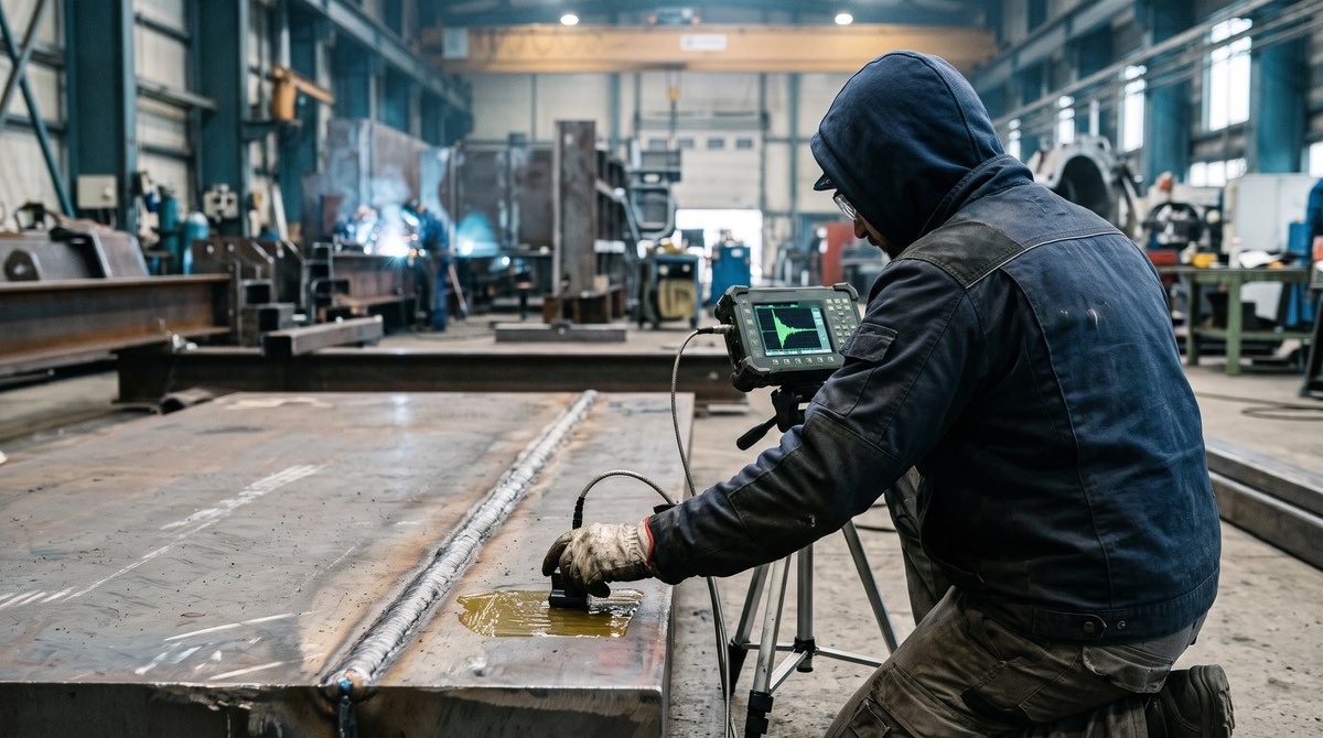
Two reports on the same 20 mm joint can record different echoes and both be right. The first operator set up the instrument on a DAC curve built from 3 mm side-drilled holes, the second on the DGS diagram of a 2 mm disk-shaped reflector, and ISO 17640 says so plainly: the permitted sensitivity-setting techniques may not give equal results. Ultrasonic testing of welds is decided almost entirely before the probe touches the steel, in the choices on reference, testing level, beam angles and frequency. Leave them to the operator and you end up with a report that is hard to defend when the customer or the inspector asks how it was obtained.
After liquid penetrant testing, magnetic particle testing and weld radiography, the series reaches the volumetric method that travels to the job site in a carrying case, seen from the point of view of whoever has to set up manual UT on butt welds in ferritic steel. The overall picture of the methods is on the non-destructive testing page.
From quality level to a verdict on the joint, one standard at a time
Everything starts on the drawing, with the quality level required for the joint under ISO 5817. From there, ISO 17635:2025, which sets the general rules for testing welds in metallic materials, leads to the method and the standards that govern it. For pulse-echo ultrasonics with conventional probes the pair is ISO 17640:2018, which says how the test is performed, and ISO 11666:2018, which says what is accepted. The link between the three levels is set out in Annex A of ISO 17635.
| ISO 5817 quality | ISO 17640 testing level | ISO 11666 acceptance level |
|---|---|---|
| B | At least B | 2 |
| C | At least A | 3 |
| D | At least A | 3, only if a specification calls for it (UT not recommended) |
So there are only two acceptance levels, 2 and 3, and they apply to full-penetration joints in ferritic steels. For quality D, ISO 11666 explains that ultrasonic testing is generally not requested. Level 1, which some people look for in specifications, exists only in the standards for techniques that size flaw height, such as ISO 19285 for phased array, because it relies on exactly that measurement.
If the specification also asks for the nature of the discontinuity, ISO 23279:2017 comes in, classifying embedded discontinuities as planar or non-planar. The consequence is significant. With characterization specified, ISO 11666 does not accept planar discontinuities and applies its amplitude levels only to non-planar ones. Without characterization, the same levels apply to any echo above the threshold. On a joint with a short, weak lack of fusion, one route leads to acceptance and the other to a repair.
There is also an edition detail to pin down in the contract. ISO 11666:2018 refers to the 2014 edition of ISO 5817, while ISO 17635:2025 came out when ISO 5817 was already in its 2023 edition, and a specification that cites standards without a year leaves open which text applies at acceptance. For radiography, the same path from quality level to rejection criterion is traced by the ISO 5817 tool for technique class and acceptance level.
What has to be decided before touching the part
Clause 6.1 of ISO 17640 lists the information to be specified before testing, and the list is longer than many purchase orders suggest. Besides levels and reference methods, it covers the manufacturing stage at which testing takes place, personnel qualification, testing for transverse discontinuities, any tandem testing to ISO 16826, parent metal testing and whether a written procedure is required.
Two of these items change the field work more than the others. The testing volume covers the weld and the parent metal on each side for the width of the heat-affected zone, or for at least 10 mm if that width is not known, and the scanning must cover all of it. If part of the volume cannot be reached from any direction, supplementary techniques have to be agreed, from dual-element probes and creeping waves to removal of the weld cap or a switch to penetrant, magnetic particle or radiographic testing. Next comes the parent metal. Before or after welding, the scanning zone has to be checked with straight-beam probes, because a lamination under the angle probe deflects the beam and hides what lies beyond it. This step can be skipped only when earlier testing shows that the angle-beam inspection is not affected.
Then there is the surface. Scanning zones must be wide enough to cover the volume, free of rust, scale and spatter, with waviness that leaves no more than 0.5 mm of gap under the probe. Along the weld toe the standard tolerates up to 1 mm, provided at least one additional beam angle is used from the affected side. In the shop these values turn into hours of grinding, and they belong in the quote before they become a surprise cost.
Frequency, beam angles and probe size follow the bevel
The frequency must be between 2 and 5 MHz, chosen on the material and the acceptance levels to be applied. ISO 17640 allows higher frequencies when depth resolution is needed for characterization to ISO 23279, and lower ones for long sound paths or highly attenuating material. For beam angles there are three rules, each with a physical reason. When the beam has to reflect off the opposite surface, the angle to the normal of that surface must stay between 35° and 70°. One of the angles must hit the fusion faces at or near normal incidence, because a lack of fusion behaves like a flat mirror and returns its echo only to a probe facing it. When two or more angles are specified, their nominal values must differ by at least 10°.
A paper published by the Institute of Welding in Gliwice, Poland (Kaczmarek, 2016), which works through Table A.1 of the 2010 edition of the standard, turns these rules into concrete choices. On a single-V groove the optimum probe angle is 90° minus the bevel angle, so 60° for a 30° bevel and 70° for a 20° bevel, while with 22.5° or 25° bevels no standard probe lands exactly on the value. At testing level B, from 15 mm upward, two beam angles are needed, with an exception between 15 and 25 mm, where one is enough if the probe frequency is below 3 MHz. The width of the scanning zone, finally, is expressed in multiples of the full skip distance, p = 2t·tanα, and for butt joints the same Table A.1 sets it at 1.25p at every testing level. On narrow qualification test plates this requirement becomes a constraint on coupon size.
Transducer size depends on the sound path. Crystals of 6 to 12 mm diameter work on short paths, while for angle-beam paths over 200 mm the standard points to 12 to 24 mm transducers. On curved surfaces the gap between probe and part is estimated with g = a²/4D, where a is the probe dimension in the direction of curvature and D the part diameter. Above 0.5 mm the wedge must be contoured, with range and sensitivity set on the adapted probe. The couplant, selected per ISO 16810, must be the same for setup and for testing, a simple requirement that is easy to forget when a bottle runs out halfway through a shift. Flaw detectors and angle-beam probes are described on the ultrasonic testing instruments and thickness gauges page.
DAC, DGS, notch or tandem: the reference moves the result
The whole setup revolves around the reference level, and ISO 17640 allows four techniques to establish it. The first uses a distance-amplitude curve (DAC) built on 3 mm side-drilled holes. The second uses the DGS system, distance-gain-size, referred to the diameter of a disk-shaped reflector equivalent to a flat-bottomed hole. The third uses a 1 × 1 mm rectangular notch, but only between 8 and 15 mm of thickness and with beam angles of 70° or more. The fourth is the tandem technique, referred to a 6 mm flat-bottomed hole and applicable only with 45° beams from 40 mm upward. Whichever technique is chosen, ISO 11666 requires it for both setup and testing.
With DGS the reference reflectors are tabulated. For shear-wave angle probes between 3 and 5 MHz the equivalent disk is 1.5 mm for thicknesses from 8 to 15 mm, 2 mm from 15 to 40 mm and 3 mm from 40 to 100 mm. Below 15 mm the tables call for 3 to 5 MHz probes, so thin plates are tested at a higher frequency. The other levels derive from the reference. The acceptance level marks the rejection boundary, the recording level sits 4 dB lower under ISO 11666, and the evaluation level indicates from which amplitude an echo must be evaluated and sized.
Setup requires two families of blocks that should not be confused. Calibration blocks No. 1 and No. 2, now covered by ISO 2400:2025 and ISO 7963:2022, are used to set and check range, probe index and beam angle. Reference blocks with side-drilled holes or notches are used to build the curve, and ISO 17640 requires holes and notches to be longer than the beam width measured at −20 dB. Where the surface and attenuation of the part differ from those of the block, the transfer correction provided by the standard applies, a decibel value that belongs in the report because on its own it can push an echo above or below the threshold. Instrument and probes, in turn, must comply with the parts of EN 12668, now superseded by ISO 22232.
A setup also ages over the course of a shift. The temperature difference between setup and testing must stay within ±15 °C, and checks must be repeated at least every 4 hours and at the end of the job. Deviations up to 2 dB require no action, and between 2 and 4 dB the setting is corrected before testing continues. A loss of sensitivity above 4 dB means repeating all testing done since the last check, while a gain above 4 dB means re-examining all recorded indications. On range the threshold is tighter, since a deviation above 2% of the range forces a repeat of the previous period's testing.
Setting up ultrasonic testing for your welds?
Tell us the material, thicknesses, bevel type and governing standard: we help you choose the flaw detector, probes and blocks, with the option of a trial on your own material. Quote within 24 hours.
Email us Message us on WhatsAppA 20 mm butt weld, from specification to setup
Take an example. Carbon steel plates 20 mm thick, a full-penetration butt weld with a 60° single-V groove, so 30° bevels, and quality level B to ISO 5817. The chain leads to testing level B of ISO 17640 and acceptance level 2 of ISO 11666. With 4 MHz probes the first choice is the 60°, which strikes the fusion faces almost head-on. The second angle, required at this thickness and frequency, can be a 45°, which meets the 10° minimum spacing and works well on the root. A 70° can help near the weld cap, if the free surface allows it.
The geometry numbers come right away. The full skip distance is about 69 mm with the 60° and 40 mm with the 45°, and with the scanning zone set at 1.25p the 60° probe needs about 87 mm of clear surface on each side of the weld. On plates held by clamping fixtures close to the weld, those nearly 9 centimeters are not always available, and it is better to know before the part is fixed in place.
For the reference you can use DGS with a 2 mm equivalent disk, the tabulated value for thicknesses from 15 to 40 mm and 3 to 5 MHz probes, or a DAC on 3 mm side-drilled holes. The recording threshold falls 4 dB below the acceptance level. What then changes how the joint is read is the grouping rule of ISO 11666, under which nearby indications, within distances the standard sets from their length and the wall thickness, are assessed as a single indication. The group length also includes the gap between them, and that figure goes back against the acceptance level.
The 6-inch pipe: curvature, access and code
The other example is a girth weld on a 6-inch pipe, 168.3 mm outside diameter and a wall of about 11 mm, in a plant designed to ASME B31.3. For normal fluid service the code requires full examination of at least 5% of circumferential welds, by random radiography or random ultrasonic testing, and for performing the ultrasonic examination it refers to ASME Section V, Article 4. If the project follows European standards instead, the reference remains ISO 17640, and the procedure must state clearly which document governs the job.
Staying with ISO 17640, between 8 and 15 mm the notch technique is also available, provided the beam angle is 70° or more, while with DGS the reference disk drops to 1.5 mm. A 70° probe on 11 mm has a full skip of about 60 mm, and the scanning zone stretches to about 75 mm per side. It is the curvature, however, that decides the wedge. With a probe 20 mm wide in the direction of curvature, g = a²/4D gives about 0.59 mm, above the 0.5 mm limit, so a wedge contoured to the diameter is needed, with range and sensitivity set again on it. A 16 mm wide probe drops to 0.38 mm and can work with a flat wedge.
On pipe-to-elbow or pipe-to-flange joints, access is often available from one side of the weld only, and in that case Table A.1 of ISO 17640 calls for two beam angles at testing level B even below 15 mm. When the required angles of incidence cannot be met, the report has to describe the scans performed, the missing coverage and the difficulties encountered, and this is a point to settle with the client before the job starts. At the root of a pipe, finally, the internal bead and the misalignment between pipe ends return geometric echoes, which are told apart from real discontinuities by plotting their position on the joint cross-section, with depth and distance from the weld centerline.
Sizing a length: who decides how it is measured
Two operators looking at the same echo can still write down different lengths if they measure in different ways. ISO 11666 sets its own method. Length is measured with the fixed-amplitude-level technique, as the distance over which the echo stays above a set threshold. Structural integrity assessments, on the other hand, often use the 6 dB drop, which measures length between the points where the echo falls to half its maximum, and the two numbers do not match.
Guidance from the UK Health and Safety Executive on ultrasonic sizing errors (2008) shows how much uncertainty is involved. For the 6 dB drop it estimates zero systematic error but a random error standard deviation of ±10 mm on length, and for through-wall height measured by the maximum amplitude method a systematic undersizing of 1 mm for each edge located, so 2 mm for an embedded flaw. How many standard deviations to add to the measurement is up to the engineer performing the structural assessment. On the 20 mm joint, where the ISO 11666 limits are expressed as multiples of thickness, ±10 mm is half the wall.
For characterization, ISO 23279 decides whether a discontinuity is planar or non-planar. True height, the figure a fracture mechanics calculation needs, is better obtained with recorded techniques such as TOFD to ISO 10863:2020 and phased array to ISO 13588:2019, which have their own acceptance criteria in ISO 15626:2018 and ISO 19285.
Which standard and which level, case by case
| Situation | Starting reference | To be set in the procedure |
|---|---|---|
| Ferritic steel 8-15 mm, quality C | ISO 17640 level A, ISO 11666 level 3 | Angle chosen on the bevel, DGS 1.5 mm (3-5 MHz) or 1 × 1 mm notch with 70° beams |
| Ferritic 15-40 mm, quality B | ISO 17640 level B, ISO 11666 level 2 | Two angles at least 10° apart, one normal to the fusion faces (up to 25 mm, one is enough below 3 MHz); DGS 2 mm or DAC on 3 mm holes |
| Ferritic 40-100 mm, quality B | ISO 17640 level B, ISO 11666 level 2 | DGS 3 mm; tandem to ISO 16826 if specified; larger transducers on long paths |
| Characterization required by the specification | ISO 23279 together with ISO 11666 | Planar discontinuities not accepted; higher frequencies if resolution is needed |
| Thickness below 8 mm | Outside ISO 17640 | Radiography, thin-wall phased array (ISO 20601) or TFM (ISO 23864) |
| Austenitic, duplex, nickel alloys, dissimilar joints | ISO 22825 for the procedure | Qualification on blocks of the actual material; testing level D by specification |
| Partial penetration, automated testing, temperature outside 0-60 °C | ISO 17640 level D | Requirements defined by the specification |
| Flaw height or recorded data required | Phased array ISO 13588 + ISO 19285, TOFD ISO 10863 + ISO 15626 | Scan plan, encoder, stated acceptance criterion |
| ASME B31.3 piping | ASME Section V, Article 4 | Code acceptance criteria, random examination extent |
Where manual UT stops
The scope of ISO 17640 is narrower than many assume. It starts at 8 mm, requires low-attenuation materials and part temperatures between 0 and 60 °C, and outside these conditions you enter testing level D, which the standard reserves for special applications and which exists only when a specification defines it.
The trickiest limit is the material. In austenitic steels, duplex grades, nickel alloys and dissimilar joints, the coarse grain and anisotropy of the weld metal deflect and attenuate the beam, and generate mode conversions that look like discontinuities on the screen. ISO 22825, in its 2017 edition, sets no acceptance levels but describes how to develop and qualify a procedure on blocks of the actual material, often with dual-element longitudinal-wave probes. On these joints the real work lies in qualification, and many specifications keep radiography as the reference method.
The third limit is the record the test leaves behind. Manual UT produces a report, not data that can be reanalyzed, and this matters when a code allows radiography to be replaced. In the ASME world the path was opened by Code Case 2235, with its technical basis published in the Journal of Pressure Vessel Technology, which judges flaws on fracture mechanics criteria, meaning height and length. That is the territory of phased array and TOFD with recorded scans, as explained in the phased array guide and in the comparison between radiography and ultrasonic testing.
A report that holds up under review
A defensible UT report lets a second operator repeat the same test. Besides joint identification and outcome, it should therefore record procedure and testing level, instrument and probes with frequency, angle and size, blocks used, reference technique with transfer correction, scanning surfaces and sides, and any areas not covered. For each recorded echo it needs position along the weld, distance from the axis and depth, amplitude relative to the reference and length, with the sizing method stated. Sign-off belongs to personnel qualified to ISO 9712 for the UT method at the appropriate level.
An ultrasonic test is only as good as the procedure that lets another operator, with another instrument, repeat it years later. If you are setting up or reviewing the inspection of your welds, the next step is to put together thicknesses, bevels, materials and standard, and choose the flaw detector, probes and blocks on that basis.
What to send us for an assessment
To work out which configuration your joints need, a few data points are enough:
- parent and filler material, with thicknesses and diameters;
- joint type and bevel geometry, with a drawing if available;
- ISO 5817 quality level or governing code (ISO 17640, ASME, other);
- access to the joint, from one or both sides, in the shop or on site;
- number of joints per month and equipment already in use;
- any requirement for recorded data or for replacing radiography.
You can send them by email to info@dipitech.com or on WhatsApp, attaching a drawing of a typical joint and the relevant part of the specification if you have them. You can also use the contact form.
With this information we help you choose the flaw detector, angle-beam probes, wedges and calibration blocks, and work out whether your joints call for a move to phased array or TOFD. The available solutions are on the page on ultrasonic instruments, flaw detectors and thickness gauges, with technical support in Italy and the option of a trial on your own material.
Request a quote
Leave your name, email, and a few lines about your application, with no obligation. We reply within 24 hours with initial technical guidance and a quote.
Frequently asked questions about ultrasonic testing of welds
Which standard applies to ultrasonic testing of welds?
For manual UT with conventional probes, ISO 17640:2018 sets techniques and testing levels, ISO 11666:2018 acceptance levels 2 and 3, and ISO 23279:2017 the characterization of discontinuities. ISO 17635:2025 links the ISO 5817 quality level to the method. Phased array and TOFD have their own standards, ISO 13588 with ISO 19285 and ISO 10863 with ISO 15626, while on ASME projects the examination follows Section V, Article 4.
What is the difference between testing level and acceptance level?
The ISO 17640 testing level A, B, C or D states how much coverage you buy, meaning the sides, angles and techniques used, and therefore the probability of detecting imperfections. The ISO 11666 acceptance level 2 or 3 states what is accepted. ISO 5817 quality B requires at least testing level B and acceptance level 2, quality C at least level A and acceptance level 3.
From what thickness can welds be tested ultrasonically?
ISO 17640 applies from 8 mm upward, on low-attenuation materials and with the part between 0 and 60 °C. Below 8 mm the options are radiography, thin-wall phased array from 3.2 to 8 mm to ISO 20601, or TFM to ISO 23864. On austenitic steels, duplex grades and nickel alloys the procedure must be developed and qualified to ISO 22825.
Can ultrasonic testing replace weld radiography?
In many cases yes, if the code or contract allows it. ASME B31.3 accepts radiography or ultrasonic testing for random examination of piping, and in the ASME pressure vessel code, Code Case 2235 opened the way to ultrasonics in lieu of radiography with criteria based on flaw height and length, the territory of phased array and TOFD with recorded data. The two methods see different imperfections, however, and the choice should be made on the expected flaw.
Who can perform ultrasonic testing of welds?
Personnel qualified and certified for the UT method to ISO 9712 or an equivalent scheme, at the appropriate level in the relevant industrial sector. ISO 17640 also requires the operator to be familiar with the problems typical of the joints being tested. As a rule, Level 2 sets up the instrument, evaluates indications and signs the report, while Level 3 approves procedures and techniques.
How much does an ultrasonic weld inspection instrument cost?
There is no single price, because cost depends on the configuration: conventional flaw detector or phased array, number and type of angle-beam probes, contoured wedges for pipe, calibration and reference blocks, reporting software. Starting from materials, thicknesses, joint type and governing standard, DIPITECH helps you choose and prepares a tailored quote within 24 hours.