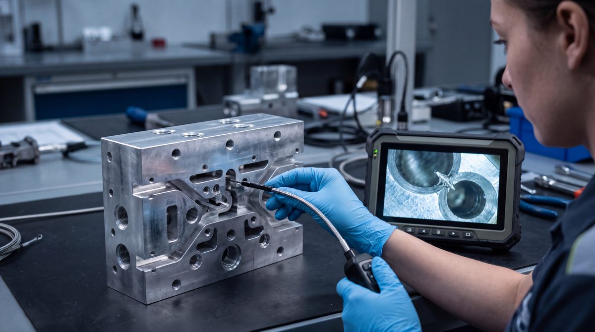
A hydraulic directional valve comes back from a customer after a few hundred hours with its spool seized. On teardown, between spool and body, there is a steel flake three tenths of a millimeter long. The block had been washed, the end-of-line sample had passed its technical cleanliness test, and the system oil met the specified class. The flake came from an intersection between two holes, where a burr bent over but still attached to the wall had survived washing and broken loose after thousands of pressure peaks. Looking inside that intersection with a videoscope before assembly would have taken a couple of minutes.
The same risk applies to hydraulic manifolds, valve bodies, pumps, engine blocks and cylinder heads, gearbox housings and aerospace components, all parts that carry fluid through drilled passages that cross each other. Only remote visual inspection reaches those passages, and the result depends on knowing what to look for and on the probe, optics and lighting chosen for those diameters and depths. The overview of the instruments is on the page about industrial borescopes and videoscopes for remote visual inspection.
A burr that stays attached passes washing and cleanliness testing
When the drill making the second passage breaks through the wall of the first, the material at the exit is not fully cut and bends inward. That is how the exit burr forms, often together with a secondary burr on the opposite edge and chips trapped in blind sections or behind plugs. Burr shape and height depend on the ratio between the two hole diameters, the intersection angle, the feed rate over the last tenths of the stroke and the material. The studies by Heisel and Schaal in Production Engineering (2008) and by Leitz, Franke and Aurich in ATZproduction (2009) describe the effect on cross-drilled holes in automotive production, where controlling burr formation is a condition for avoiding a later deburring step. The CIRP review by Aurich, Dornfeld and colleagues (2009) points out that deburring is a costly operation that adds no value to the part, and that preventing the burr in the first place is the better path.
The trouble with burrs at intersections lies in how they slip past cleanliness checks. ISO 4406 codes the number of solid particles in the oil of a circuit, so it measures the state of the fluid. On components, ISO 18413 for hydraulics, ISO 16232 and the VDA 19.1 guideline for automotive describe how particles are extracted by rinsing or spraying, filtered and counted. What gets measured is whatever comes off during extraction. A firmly attached burr stays on the part, the analysis filter comes out clean and the component passes. ISO 16232 also states explicitly that visual checks, being non-quantitative methods, fall outside its scope. The videoscope therefore works alongside cleanliness testing without replacing it, and it covers exactly the contaminants the test cannot see as long as they stay attached.
What the videoscope has to see at the intersection
The first reference is the drawing. ISO 13715 sets out how edges of undefined shape are indicated, that is, whether an edge may carry a burr and how large, or whether it must be chamfered or rounded within a given value. If the drawing of the intersection carries such an indication, the check has a measurable criterion. If it does not, agree on one with the customer before you start, because "burr-free" said out loud is read in very different ways.
The indications to look for are few and recurring. The exit burr appears as a lip of metal standing proud of the wall of the main passage, often brighter than its surroundings because it reflects the probe light. The flag burr is a thin flap attached on one side, the most dangerous kind because vibration breaks it off. Chips collect in blind ends, at diameter changes and behind ball plugs. After thermal, electrochemical or brush deburring, the inspection checks the edge radius obtained and any process residue, such as slag and oxides.
| Hole geometry | Typical access | Probe choice |
|---|---|---|
| Short straight hole, intersection near the entry | Direct, in line | Rigid borescope with side view, or flexible probe with a 90° tip |
| Long passage with a deep intersection | From the main passage | Flexible probe longer than the passage, side view to see the intersection wall |
| Small hole, a few millimeters | Tight, no room to bend | Slim probe with side view, limited or no articulation |
| Medium or large hole with several intersections | Room to bend the tip | Four-way articulating probe, forward and side optics |
| Blind end, plugs, diameter changes | At the bottom of the passage | Forward optics with close focus |
Diameter, depth and angle: how to choose the probe
The probe is set by the narrowest passage it has to go through, with some clearance. A 4 mm probe fits comfortably in a 6 mm hole, a 4 mm hole needs something under 3, and for holes of one or two millimeters there are probes below one millimeter, with optics and lighting scaled down accordingly. Length must exceed the depth of the farthest intersection, plus the section left outside for handling. In a large manifold, intersections at the bottom of a 300 mm passage are nothing unusual.
Articulation is there to point the tip, but bending takes room. In a hole a few millimeters across the tip cannot turn to face the wall, and an articulating probe ends up scraping along it. Side view works better here, with a prism that turns the line of sight by 90° and frames the wall while the probe travels straight. In practice you enter from the main passage, bring the side-view optic level with the intersection and rotate the probe on its axis to sweep the whole perimeter of the opening. It helps to know the drilling sequence, because the exit burr forms in the passage drilled first, at the point where the second tool broke into it.
Focus distance and depth of field matter as well. In a small hole the wall is a few millimeters from the optic, and a lens designed for long distances shows only a blur. Tight holes call for close-focus optics, which have a shallow depth of field, while in large passages a deeper field keeps the whole intersection sharp. That is why, when the diameters to inspect vary widely, interchangeable probes and optics on the same instrument are worth more than a high-resolution sensor.
Light and glare on machined aluminum
Machined aluminum and steel walls are highly reflective, and the LED at the probe tip, a few millimeters from the surface, easily burns out the very spot where the burr sits. Lowering intensity, reducing gain and changing the viewing angle almost always work better than adding light. At an intersection a burr is often recognized by its shadow more than by its surface, so grazing light coming from the side makes it stand out. Before inspection the holes must be cleaned of cutting oil and coolant, because an oil film or a drop in a blind end throws reflections that get mistaken for defects.
Got a manifold or valve with holes that are hard to inspect?
Send us hole diameters and depths, material and your burr criterion: we help you choose a videoscope that fits your holes, with a trial on your part. Quote within 24 hours.
Email us Message us on WhatsAppMeasuring the burr as well as seeing it
When the drawing sets a maximum height, the image alone is not enough. Videoscopes with stereo or 3D measurement reconstruct the surface in view and let you measure burr height relative to the wall, its length, or the area of a flake. Uncertainty grows with the distance between optic and object, so the measurement should be taken as close as possible and repeated. Measurement optics have their own bulk, though, and often do not fit the smallest holes. In those cases a known dimension in the image serves as reference, for instance the diameter of the secondary hole shown on the drawing, and the burr is estimated by comparison, with the report stating that it is an estimate.
Documentation is the part the customer sees. Each intersection should be identified by a number on the part map, and for each one you record the photo, the clock position and the depth read from the probe markings. A short video following the probe from the entry to the intersection is worth more than many photos when you have to prove to a customer or an auditor that the passage is clear. Filed under the batch number, photos and videos also become the basis for handling a complaint months later.
Sampling inspection between incoming checks and end of line
On a manifold with twenty intersections a full check takes time, and it does not always make sense on every part. At incoming inspection of parts machined by a supplier, the work is done lot by lot, with an attribute sampling plan such as those in ISO 2859-1, tightening the check when nonconformities appear. At end of line, 100% inspection is reserved for critical intersections, those feeding pilot valves, servo valves or sealing seats, while the rest is sampled. A chart of burr frequency per intersection soon shows whether a problem comes from a worn tool or from a drilling program that needs correcting.
Visual inspection depends heavily on who does it. The study by See in Human Factors (2015), carried out with inspectors of precision parts, found that on average they caught 85% of defective parts and wrongly rejected 35% of good ones, with results varying widely from one defect type to another. That calls for reference images showing acceptable and rejectable examples, a fixed sequence of intersections, and operators trained to the general principles of visual testing in EN 13018, with qualification under ISO 9712 when the customer requires it.
The business case rests on what a burr does once it reaches the field: a warranty return, a valve torn down at the customer's site, sometimes downtime on a machine that is not even yours. A few minutes of sampling inspection cost far less, and the documentation it produces also helps close disputes quickly.
Mirror, rigid borescope or CT: when other tools are needed
A mirror and a lamp are still useful for edges at the entry, a few millimeters from the surface, and they reach no further. A rigid borescope with side view gives excellent images in a short straight hole and costs less than a flexible videoscope, but it cannot follow a passage that changes direction. Industrial CT sees intersections with no access needed, and in aluminum manifolds of moderate size it shows burrs and chips throughout the volume. On large steel blocks achievable resolution drops and scan times rise, so CT is used in development, on first articles or for failure analysis through the industrial CT scanning service, while routine inspection stays with the videoscope.
For a broader look at choosing the instrument, from probe families to ergonomics, see the guide on how to choose an industrial videoscope. At intersections, though, the choice starts from two measurements, the narrowest hole you have to pass through and the depth of the farthest intersection. Diameter, length, optics and articulation follow from there, and a trial on the real part shows whether the burr can be seen as needed.
What to send us for an assessment
To recommend a videoscope that suits your holes we only need a few details:
- drawing or sketch of the part with the passages and intersections to check;
- minimum hole diameter, maximum depth and intersection angles;
- material and finish, including any deburring already done;
- burr acceptance criterion (drawing callout or agreement with your customer);
- number of parts to inspect per day, at incoming inspection or end of line;
- whether burr measurement is needed and the report format you deliver.
You can send them by email to info@dipitech.com or on WhatsApp. You can also use the contact form.
With these details we help you choose among industrial videoscopes with probes from under one millimeter to 6 mm and side view, arrange a trial on your part and send you a quote within 24 hours, with technical support in Italy. The full picture of remote visual inspection is on the page about industrial borescopes and endoscopes.
Request a quote
Leave your name, email, and a few lines about your application, with no obligation. We reply within 24 hours with initial technical guidance and a quote.
Frequently asked questions about inspecting burrs and chips in cross-drilled holes
Why don't cleanliness tests catch burrs in cross-drilled holes?
Technical cleanliness tests under ISO 16232, VDA 19.1 or ISO 18413 count the particles that come off during extraction. A burr still attached to the wall stays on the part, the analysis filter comes out clean and the component passes. The burr can break loose later in service, under vibration and pressure peaks. A videoscope is how these attached contaminants are seen.
What probe diameter do I need to inspect a hole?
The narrowest passage to go through sets the diameter, with some clearance: a 4 mm probe fits comfortably in a 6 mm hole, a 4 mm hole needs a probe under 3 mm, and for holes of one or two millimeters there are probes below one millimeter. Length must exceed the depth of the farthest intersection plus the section needed for handling.
Articulating probe or 90° side view?
In holes a few millimeters across the tip has no room to bend, so side view works better: it frames the intersection wall while the probe travels straight and rotates on its axis. Four-way articulation becomes useful in medium and large holes with several intersections, where there is room to point the tip.
Can a videoscope measure burr height?
Yes, with videoscopes that offer stereo or 3D measurement, which reconstruct the surface and measure burr height relative to the wall. Uncertainty grows with distance, so measure from close up. In the smallest holes measurement optics often do not fit, and the burr is estimated by comparison with a known dimension, stating so in the report.
What is the difference between a borescope and an industrial endoscope for these checks?
In everyday use the terms overlap. A rigid borescope has lens optics and gives excellent images in a short straight hole, but cannot follow a passage that changes direction. A videoscope, or video borescope, has a flexible probe with a camera at the tip and often articulation, and reaches deep intersections in hydraulic manifolds and engines.
How do I request a quote for a videoscope suited to my holes?
We need the drawing or a sketch of the passages to inspect, minimum hole diameter and maximum depth, material, burr acceptance criterion and number of parts per day. With these details DIPITECH helps you choose the videoscope, arranges a trial on your part and prepares a quote within 24 hours.